A line filter chosen for a 50-ohm attenuation plot can still trip an earth-leakage device, or leave differential noise in place after the Y capacitors were cut to save that leakage. The two modes do not share one component.
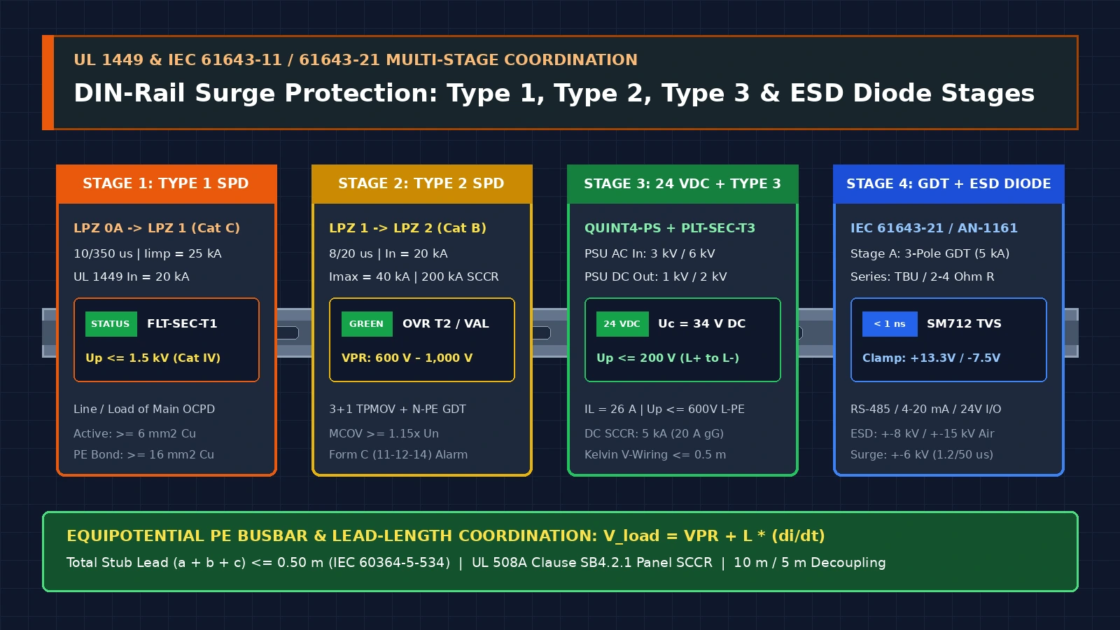
Read common mode and differential mode as separate currents, then size Cy from leakage before you read a catalog curve. TDK’s EMC-filter technical note assigns X capacitors and series inductors to differential mode, and a current-compensated choke plus Y capacitors to common mode. Schaffner’s RB-choke design note calculates the line-frequency current through Cy and then shows, on a CISPR 17 bench, what happens to each mode when Cy is reduced and when a second Cx is added. The kiosk power-input checklist keeps the equipment’s AC boundary on its own line, while upstream high-energy transient clamping ahead of the filter is covered in the DIN-rail Type 1, 2, and 3 surge protection device coordination guide. This page starts after that boundary is known. It sits with the other power and protection notes.
| Choice | What it changes | Dominant failure mode | Prevention |
|---|---|---|---|
| Current-compensated choke | High inductance for common mode; leakage inductance only for differential mode | Differential noise left on the lines because the core flux cancelled | Add Cx. Do not raise L and expect differential attenuation |
| Y capacitor to PE | Common-mode path at higher frequency | Earth current rises with Cy and trips the leakage limit | Compute Ilk and cut Cy, or pick the high-inductance option in the note |
| X capacitor line to line | Differential-mode path | A single Cx misses the projected differential attenuation once parasitics appear | Schaffner’s second build added a load-side Cx and differential attenuation rose |
| Catalog curve | Comparison at the stated impedance | 50-ohm data treated as the installed source and load | Keep the curve for ranking. Measure in the equipment |
The two modes use different parts
TDK’s technical information sorts conducted interference by how it travels. Up to several hundred kilohertz it is mainly differential, which the note also calls symmetrical: between phase and neutral, or between phases. At higher frequency the same note treats it as mainly common-mode, or asymmetrical, because parasitic capacitance and inductance between conductors grow with frequency. X capacitors, connected between the phase conductors, and series inductors are the differential measures. Common-mode measures are a current-compensated choke and Y capacitors from the live conductors to reference earth, which only work with the earthing and wiring the note requires.
The choke’s winding direction is the split. TDK states that with opposite winding directions the magnetic fluxes of the differential operating current cancel, so the inductance for that current is theoretically zero. Leakage fields leave a small leakage inductance. The same choke is a high inductance for common-mode current, because those currents do not cancel. A larger choke is therefore not, by itself, a differential-mode fix.
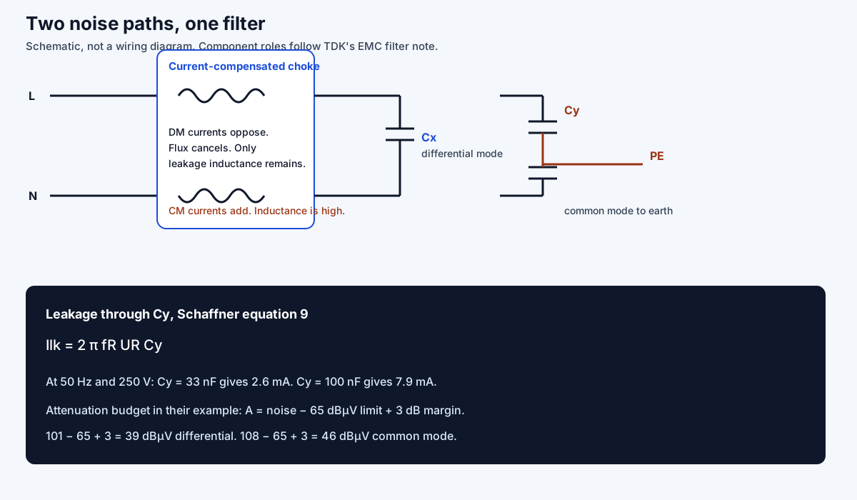
Takeaway: Name the mode before you add a part. Cx and leakage inductance serve differential mode. The choke’s main inductance and Cy serve common mode.
Leakage current sets the largest Cy you can keep
Y capacitors pass a line-frequency current to earth in a fault-free circuit. TDK defines filter leakage current ILK, citing DIN EN 60939-3, as that current at rated frequency. The same section says the catalog figure is a calculated comparison value from Annex A of IEC 60939-3, for a filter with no load on the output, and that the actual current in an application cannot be specified because it depends on many parameters. A measurement under IEC 60990, which TDK distinguishes as touch current and protective-conductor current, does not usually match the catalog calculation. Cable capacitance, motor windings, and other converters add their own earth current on top of ILK.
Schaffner’s equation 9 for the single-phase case in the RB-choke note is:
Ilk = 2 π fR UR CyThe note prints the results at a 250 V rating: Ilk = 2.6 mA when Cy = 33 nF, and Ilk = 7.9 mA when Cy = 100 nF. Substituting the 50 Hz mains frequency reproduces those printed results:
Ilk = 2 π × 50 × 250 × 33×10⁻⁹ = 0.00259 A = 2.6 mA
Ilk = 2 π × 50 × 250 × 100×10⁻⁹ = 0.00785 A = 7.9 mA
Later in the same note, a 7.9 mA result is treated as unacceptable where the applied requirement is 3.5 mA, with DIN VDE 0701-0702 named as an example of a standard that can impose such a limit. The note’s response is to reduce Cy or to move to the high-inductance choke. It does not publish a universal milliamp limit. The 3.5 mA figure is the requirement inside that example.
Rules of thumb: If calculated Ilk is above the leakage limit the equipment must meet, Cy is already too large. In Schaffner’s example that limit is 3.5 mA, so 7.9 mA fails and 2.6 mA is the value they kept. If the catalog ILK is the only number on the table, treat it as TDK’s comparison figure, then measure touch current to the standard the product actually cites.
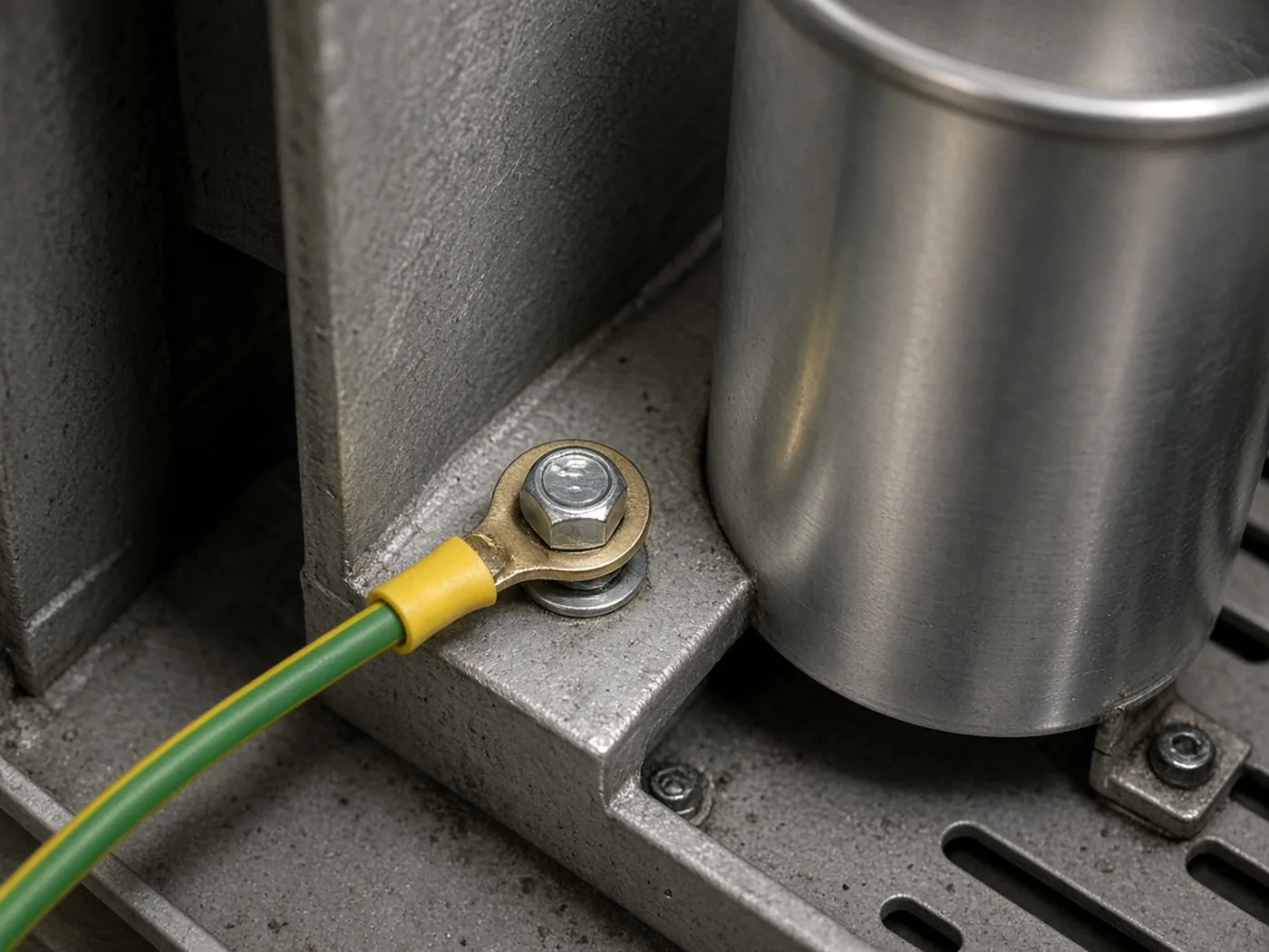
Takeaway: Write Ilk, the Cy that produced it, and the limit you are held to. A larger Y capacitor is not free attenuation.
Attenuation is a budget, then a bench result
Schaffner’s worked example uses the quasi-peak limit of 65 dBµV from IEC/EN 61000-6-3. Differential noise in the example is 101 dBµV at 180 kHz. With a 3 dB margin the required differential attenuation is:
A = noise − limit + margin
A_DM = 101 − 65 + 3 = 39 dBµV
The note’s assumed common-mode noise is 108 dBµV at 180 kHz, with a 3 dBµV margin, so:
A_CM = 108 − 65 + 3 = 46 dBµVFrom a 40 dB/decade LC slope, the note places the differential corner at 19 kHz and the common-mode corner at 12.7 kHz. Those corners belong to this noise pair. They are not a default for every supply.
The note then builds two filters and measures them to CISPR 17 in the Schaffner lab.
| Build | Capacitors | What the lab report says at 180 kHz |
|---|---|---|
| RB6522-16-1M0 | Cx = 4.7 µF, Cy = 100 nF | Differential attenuation 39 dBµV on the 9th harmonic. Common-mode attenuation about 45 dBµV. Above 300 kHz, parasitics slow the differential rise |
| RB8522-16-3M0 | Cx = 1.5 µF, Cy = 33 nF | Differential attenuation 30 dBµV, short of the 39 dBµV projection. Common-mode attenuation about 44 dBµV |
| Same low-leakage idea with a second Cx | Extra Cx = 1.5 µF | Differential attenuation about 63 dBµV. Common-mode attenuation stayed at 44 dBµV |
Cutting Cy from 100 nF to 33 nF is what brought leakage from 7.9 mA to 2.6 mA. It also dropped differential attenuation below the projection until a second X capacitor was added. Common-mode attenuation stayed near 44 dBµV, still short of the 46 dBµV budget in the example. The note’s own conclusion is that the theoretical corner is not the installed result: parasitic capacitance, leakage fields, and coupling between the choke and the line-side Cx show up above a few hundred kilohertz.
The layout rules in that note are part of the same result. Filtered and unfiltered paths are not allowed to cross. The power path goes to the X-capacitor pins. Input and output stay apart. A choke pinout that forces the wires to cross raises coupling even when the inductance value looks right.
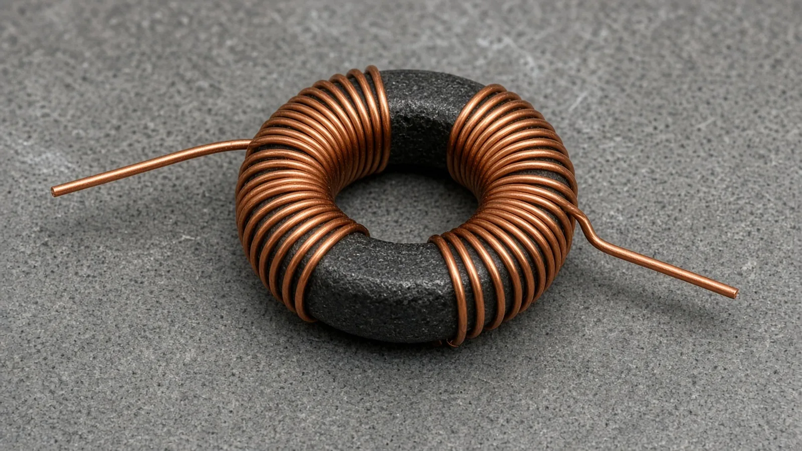
Rule of thumb: If differential attenuation on the CISPR 17 plot is below the budget after Cy was cut, add Cx before you add more common-mode inductance. Schaffner’s 33 nF build moved from 30 dBµV to about 63 dBµV at 180 kHz when the second Cx went in, and the common-mode number did not move.
Takeaway: Write the noise, the limit, and the margin as three numbers. Then check which mode the lab curve actually moved.
What a wrong mode costs
Using the 100 nF Y capacitor in Schaffner’s example spends 7.9 mA of earth current to buy a differential result the 33 nF build later matched, and beat, with an extra X capacitor at 2.6 mA. The 5.3 mA difference is the leakage you pay for a capacitor that was doing the other mode’s job:
7.9 mA − 2.6 mA = 5.3 mAThat 5.3 mA is not a product specification. It is the gap between the two published points in one application note. If the installation limit is the 3.5 mA used in that note, the 7.9 mA design is already a redesign, including another CISPR 17 pass. The heat and the retest sit on the differential problem that Cx was meant to solve.
A catalog ILK that is only a comparison value creates a second cost. TDK says the calculated ILK and an IEC 60990 measurement diverge. Selecting a filter because its datasheet milliamp is under the limit, then failing the product leakage test, repeats the whole attenuation check. Record both numbers when you have them. Do not let the catalog figure stand in for the measurement.
Takeaway: The expensive miss is a Y capacitor spent on differential noise. Compute Ilk, then spend Cx on the differential budget and Cy only on the common-mode budget that remains inside the leakage limit.
Copy one selection row
| Field | Write |
|---|---|
| Mode that fails the limit | Differential, common-mode, or both, with the frequency |
| Noise at that frequency | dBµV, and whether it is measured or assumed |
| Limit and margin | For the Schaffner example, 65 dBµV quasi-peak and 3 dB |
| Required attenuation | Noise − limit + margin, per mode |
| Cy and Ilk | Capacitance, voltage, frequency, and the calculated milliamp |
| Leakage limit in force | The standard and the number it imposes, or “not yet stated” |
| Cx | Line-side and load-side values |
| Choke | Part, inductance, and whether it is the low-leakage or high-inductance version |
| Bench | CISPR 17 or the equipment test, and which mode moved |
How this page was checked
TDK Electronics’ EMC-filter technical information supplies the mode split, the roles of X and Y capacitors and the current-compensated choke, and the statement that catalog leakage current is a calculated comparison value under the EN 60939 model. Schaffner’s application note “EMC/EMI Filter Design with RB Common-Mode Chokes” supplies equation 9, the 2.6 mA and 7.9 mA results, the 65 dBµV example limit, the 39 and 46 dBµV budgets, and the CISPR 17 results for RB6522-16-1M0 and RB8522-16-3M0. The 50 Hz substitution is the arithmetic that reproduces Schaffner’s printed milliamp figures.