Installing a single AC feeder arrester without downstream stage decoupling or lead-length control leaves a 24 V DC control bus exposed to inductive voltage drops that damage PLC power supplies and fieldbus transceivers. An uncoordinated surge protection device (SPD) can also derate an entire UL 508A control panel’s Short-Circuit Current Rating (SCCR) from 65 kA down to 5 kA or overload a downstream varistor when a primary spark gap fails to ignite.
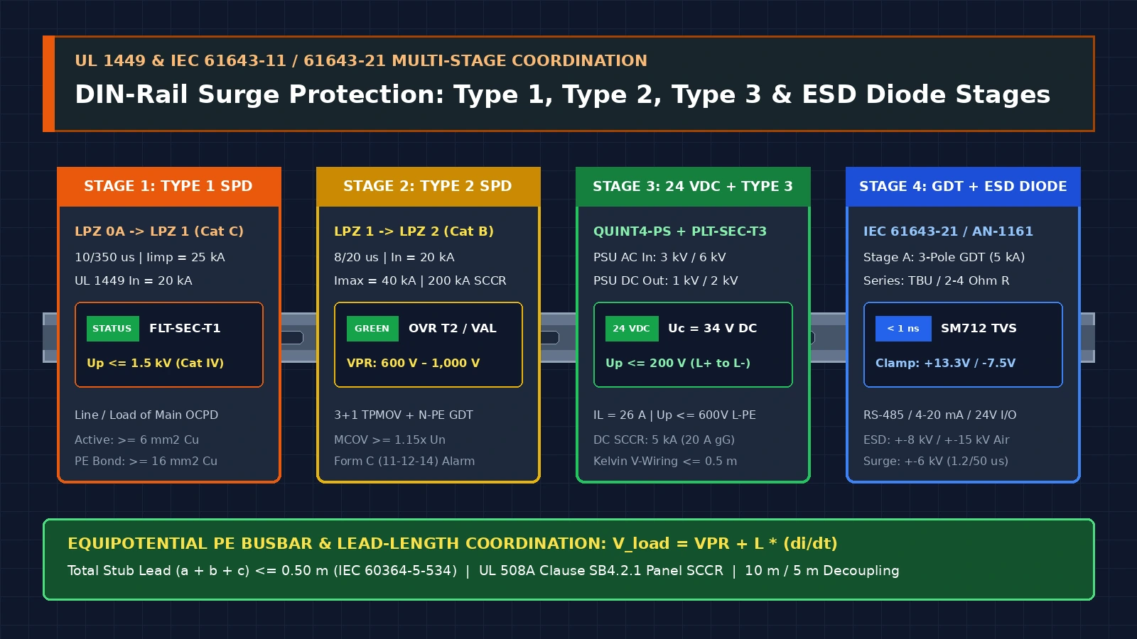
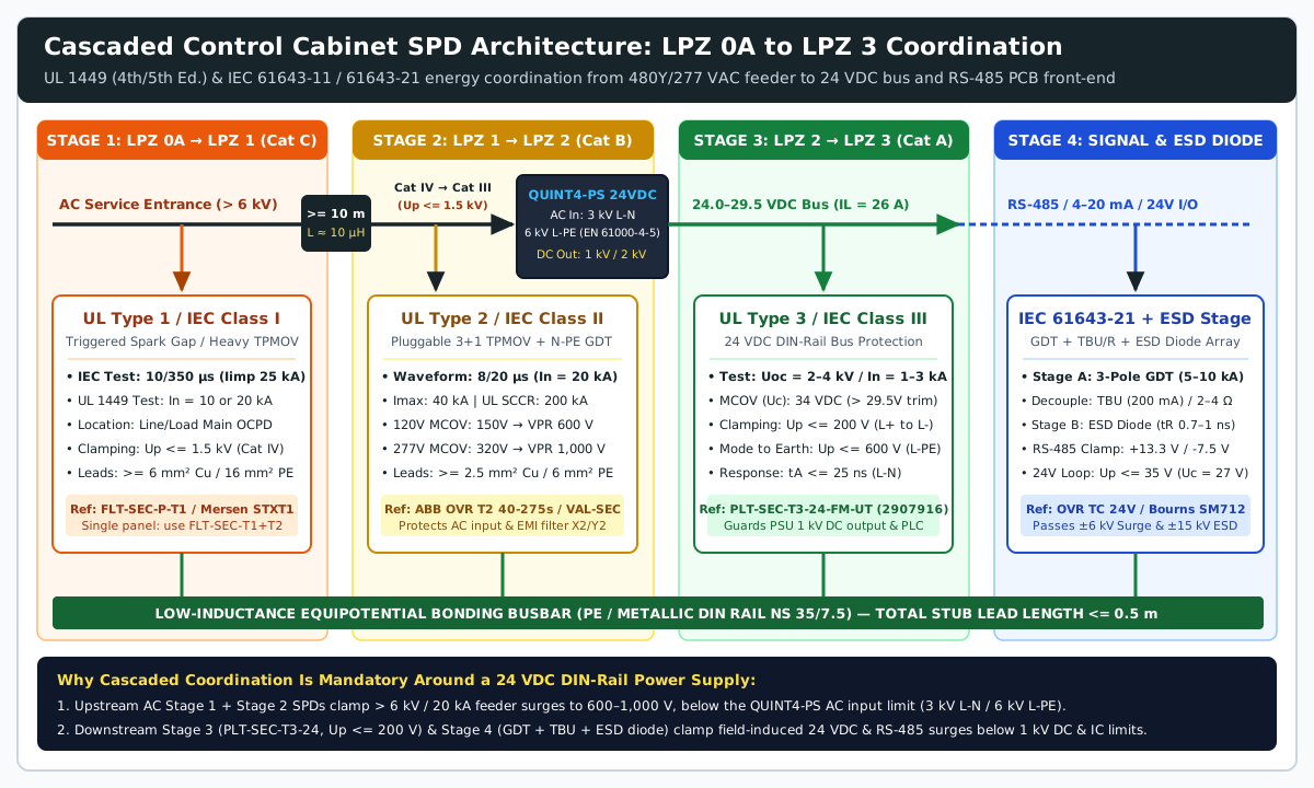
Effective DIN rail SPD coordination cascades four matched clamping zones: a Type 1 lightning arrester at the service entrance, a Type 2 thermally protected varistor on the AC feeder, a Type 3 protector on the 24 V DC DIN rail power supply output, and a gas-discharge-tube plus ESD protection diode stage on field I/O. Sizing each stage requires matching Maximum Continuous Operating Voltage (MCOV >= 1.15× Un), keeping total stub lead length at or below 0.5 m (IEC 60364-5-534), and verifying UL 508A Supplement SB SCCR selectivity across all power and protection engineering records and related technical guides.
| SPD Tier / Class | Installation Zone (IEEE C62.41.2 / LPZ) |
Standard Test Waveform & Rating | Primary Clamping Topology | Typical VPR / Up Clamping Level |
Representative Industrial Part |
|---|---|---|---|---|---|
| UL 1449 Type 1 / IEC 61643-11 Type 1 (Class I) | Line or load side of main service disconnect (Cat C / LPZ 0A → LPZ 1) |
UL: In = 10 kA or 20 kA (8/20 µs); IEC: Iimp = 12.5–25 kA/pole (10/350 µs) |
Triggered encapsulated spark gap or high-energy TPMOV array | VPR: 600 V – 1,500 V (Up <= 1.5 kV) → drops transient below Cat IV (6 kV / 4 kV) |
Phoenix Contact FLT-SEC-P-T1 / Mersen STXT1 |
| UL 1449 Type 2 / IEC 61643-11 Type 2 (Class II) | Load side of service OCPD, control panel AC feeder (Cat B / LPZ 1 → LPZ 2) |
UL: In = 3, 5, 10, or 20 kA (8/20 µs), Imax = 40–80 kA |
Thermally protected MOV (TPMOV) + N-PE gas discharge tube (GDT) |
VPR: 600 V (120 V), 1,000 V (277 V), 1,700 V (480 V) → drops below Cat III (4 kV / 2.5 kV) |
ABB OVR T2 40-275s P TS U / Phoenix VAL-SEC-T2 |
| UL 1449 Type 3 / IEC 61643-11 Type 3 (Class III) | Point of utilization >= 10 m (30 ft) from service panel; 24 V DC din rail power supply bus (Cat A / LPZ 2 → LPZ 3) |
Combination wave Uoc = 2–6 kV (1.2/50 µs) / Isc = 1–3 kA (8/20 µs) |
Hybrid MOV + suppressor diode + GDT (PE decoupling) |
Up <= 200 V (L+/L-) & <= 600 V (L-PE) on 24 V DC bus; VPR 330–700 V on 120 V AC |
Phoenix Contact PLT-SEC-T3-24-FM-UT (2907916) |
IEC 61643-21 (C1/C2/D1) + IEC 61000-4-2/4/5 Signal & Data SPD |
24 V DC discrete I/O, 4–20 mA analog loops, RS-485 / CAN fieldbus (LPZ 2 → LPZ 3 / PCB front-end) |
1.2/50 µs–8/20 µs up to 5–10 kA (GDT) + 0.7–1 ns ESD (±8 kV contact / ±15 kV air) |
Stage 1: 3-pole GDT → Decoupling R / inductor / TBU → Stage 2: esd protection diode / TVS (< 1 ns) |
Up <= 35 V (24 V loop) or +13.3 V / -7.5 V (RS-485 bus) |
ABB OVR TC 24V US / Bourns 2038-15 GDT + TBU-CA065 + CDSOT23-SM712 |
Why Single-Stage Surge Suppression Fails in Industrial Control Panels
No single surge protective element can simultaneously absorb tens of kiloamperes of lightning current and clamp transient voltage low enough to protect a 24 V DC PLC backplane or a 3.3 V differential fieldbus transceiver. Industrial enclosures face three distinct transient regimes whose time scales and specific energy levels span six orders of magnitude:
- Direct and Partial Lightning Impulse Currents (
10/350 µsWaveform): Defined byIEC 61643-11for Class I (Type 1) arresters at theLPZ 0AtoLPZ 1service entrance boundary, the10/350 µsimpulse reaches peak currents of12.5 kAto25 kAper pole (50–100 kAtotal) and decays to half-amplitude over350 µs(Phoenix Contact TRABTECH Basics 5131327). Because specific energy (W/R = ∫ i² dt) scales with pulse duration, a10/350 µslightning current carries10×to20×more destructive thermal energy than an8/20 µsswitching surge of identical peak current. - Inductive Switching Surges and Indirect Lightning Transients (
1.2/50 µsVoltage /8/20 µsCurrent): Generated by utility capacitor-bank switching, variable-frequency drive (VFD) contactor interruption, or inductive coupling into building feeders (IEEE C62.41.2Category B /LPZ 1toLPZ 2). As quantified in Bourns and Analog Devices Application Note AN-1161, anIEC 61000-4-5surge (1.2 µs ± 30%voltage rise time,50 µs ± 20%half-value duration;8/20 µsshort-circuit current) delivers3to4orders of magnitude (1,000×to10,000×) more pulse energy than electrostatic discharge (ESD) or electrical fast transient (EFT) bursts. - Sub-Nanosecond ESD (
IEC 61000-4-2) and EFT Bursts (IEC 61000-4-4): AnIEC 61000-4-2ESD pulse rises intR=0.7 nsto1.0 nswith a60 nsduration (30 Apeak at Level 4:±8 kVcontact /±15 kVair discharge), while anIEC 61000-4-4EFT burst rises in5 ns ± 30%with a50 ns ± 30%pulse width repeated at5 kHzor100 kHz(Bourns/ADI AN-1161). These fast edges contain only tens of millijoules of energy but puncture gate oxides before a microsecond-class power varistor or gas tube can fully ionize.
When a 480Y/277 V AC or 240 V AC Type 2 feeder arrester clamps a 20 kA (8/20 µs) surge, its UL 1449 Voltage Protection Rating (VPR) leaves 600 V to 1,200 V of residual let-through voltage on the AC bus (ABB UL 1449 Technical Catalog 1SXU430100C0201). That 600–1,200 V clamping ceiling protects upstream AC disconnect insulation and prevents dielectric breakdown across the X2 line-to-line and Y2 line-to-ground safety capacitors inside an AC line filter—complementing the continuous 150 kHz to 30 MHz attenuation analyzed in the common-mode vs. differential-mode EMI filter selection guide. However, 600 V to 1,200 V of residual transient voltage—compounded by surges induced directly onto 24 V DC field wiring—will destroy unprotected 24 V DC sensor ports and serial transceivers unless stepped down by downstream Type 3 and PCB-level protection stages.
Takeaway: Coordinate surge protection across four progressive zones so high-energy 10/350 µs and 8/20 µs impulses are diverted to earth at the AC entrance while downstream Type 3 and semiconductor stages clamp residual voltage below component immunity thresholds.
UL 1449 vs. IEC 61643-11/21 Classification: Type 1, Type 2, Type 3, and Signal SPDs
North American industrial control panels are governed by UL 1449 (4th/5th Edition) and UL 508A (Standard for Industrial Control Panels), while international machinery follows IEC 61643-11 (low-voltage power SPDs), IEC 61643-21 (telecommunications and signaling SPDs), and IEC 60664-1 (insulation coordination overvoltage categories). Mapping ul 1449 type 1 vs type 2 vs type 3 spd designations directly to IEEE C62.41.2 location categories and IEC Lightning Protection Zones (LPZ) prevents misapplication across service entrances, branch feeders, and 24 V DC rails.
Stage 1: UL 1449 Type 1 / IEC 61643-11 Class I (Service Entrance, LPZ 0A to LPZ 1)
Under UL LLC’s UL 508A / UL 1449 Certification Guidelines and Mersen Technical Note TT-SPN6, a Type 1 SPD is a permanently connected device certified for installation between the secondary of the service transformer and the line side of the service equipment overcurrent device, as well as the load side, without requiring an external overcurrent protective device. It corresponds to IEEE C62.41.2 Location Category C (outdoor and service-entrance conductors exposed to direct or partial lightning currents).
In UL 1449 Section 40.7.1, Type 1 SPDs must pass the Nominal Discharge Current (In) operating duty test at In = 10 kA or 20 kA (8/20 µs current wave): while energized at its full Maximum Continuous Operating Voltage (MCOV), the SPD is subjected to 15 impulses divided into 3 groups of 5 impulses (<= 1 minute ± 15 s between pulses, with 30 to 35 minutes between groups during which MCOV remains applied for 15 minutes after the 5th and 10th surges and 30 minutes after the 15th surge) (Mersen TT-SPN6). Where a facility requires a UL 96A Lightning Protection System Master Label, the SPD must be verified at the maximum In = 20 kA rating (Mersen TT-CPN4). Under IEC 61643-11, Class I / Type 1 arresters such as the Phoenix Contact FLASHTRAB FLT-SEC-P-T1 use encapsulated triggered spark gaps (Iimp = 25 kA per pole at 10/350 µs) with Safe Energy Control to quench mains follow-current without tripping upstream fuses, clamping transients below IEC 60664-1 Overvoltage Category IV (6,000 V on 277/480 V or 230/400 V systems; 4,000 V on 120–240 V systems) with Up <= 1.5 kV (Phoenix Contact TRABTECH Basics 5131327).
Stage 2: UL 1449 Type 2 / IEC 61643-11 Class II (Distribution & Panel Feeder, LPZ 1 to LPZ 2)
A Type 2 SPD is permanently connected on the load side of the service equipment overcurrent device, including sub-distribution switchboards and the main incoming AC feeder of an industrial control cabinet (IEEE C62.41.2 Category B; LPZ 1 to LPZ 2) (UL SPD Guidelines, Mersen TT-SPN6). UL 1449 assigns Type 2 SPDs a verified Nominal Discharge Current rating of In = 3 kA, 5 kA, 10 kA, or 20 kA (8/20 µs), with maximum single-impulse discharge ratings (Imax) typically reaching 40 kA to 80 kA (ABB Catalog 1SXU430100C0201).
Industrial DIN-rail Type 2 arresters—such as the ABB OVR T2 40-275s P TS U, Phoenix Contact VALVETRAB VAL-SEC-T2, and Mersen Surge-Trap STXR—combine pluggable Thermally Protected Metal Oxide Varistor (TPMOV) cartridges between phases and neutral (L1/L2/L3 to N) with a high-current Gas Discharge Tube (GDT) between Neutral and Protective Earth (N-PE in a 3+1 circuit) (Mersen TT-SPN6, Phoenix Contact TRABTECH Basics). This stage reduces transient overvoltages below IEC 60664-1 Overvoltage Category III (4,000 V on 277/480 V systems; 2,500 V on 120–240 V systems) and Category II (2,500 V / 1,500 V), delivering a clamped VPR of 600 V on 120 V AC feeders and 1,000 V on 277/480Y V feeders (ABB Catalog 1SXU430100C0201).
Stage 3: UL 1449 Type 3 / IEC 61643-11 Class III (Point-of-Utilization & 24 V DC DIN Rail Power Supply Bus, LPZ 2 to LPZ 3)
Under UL 1449, Type 3 SPDs are point-of-utilization devices installed at a minimum conductor length of 10 m (30 ft) from the electrical service panel to the protected equipment, excluding the leads used to attach the SPD (IEEE C62.41.2 Category A; LPZ 2 to LPZ 3) (UL SPD Guidelines, Mersen TT-SPN6). Tested with a 1.2/50 µs open-circuit voltage (Uoc = 2 kV to 6 kV) and 8/20 µs short-circuit current (Isc = 1 kA to 3 kA) combination wave generator, Type 3 DIN-rail modules protect IEC 60664-1 Category I sensitive electronic loads (<= 1,500 V / 800 V).
In industrial automation cabinets, Type 3 coordination is critical around the din rail power supply—both on its AC input and on its 24 V DC secondary bus (for system-level AC vs. DC power boundary documentation, see the AC-DC power supply boundary checklist). Examine the verified surge immunity parameters of the Phoenix Contact QUINT4-PS/1AC/24DC/5 (2904600, 24 V DC / 5 A, 120 W) primary-switched power supply (QUINT4-PS/1AC/24DC/5 Datasheet):
- AC Primary Surge Immunity (
EN 61000-4-5Criterion A):3 kVsymmetrical (Line-to-Neutral, Test Level 4) and6 kVasymmetrical (Line/Neutral-to-PE, Test Level 4), backed by an internal varistor, a gas-filled surge arrester, and an internal6.3 Aslow-blow input fuse. - 24 V DC Secondary Output Surge Immunity (
EN 61000-4-5Criterion A):1 kVsymmetrical (L+toL-, Test Level 3) and2 kVasymmetrical (L+/L-toPE, Test Level 3), withEN 61000-4-4EFT burst immunity of4 kVon the AC input and2 kVon the DC output, andEN 61000-4-2ESD immunity of8 kVcontact /15 kVair discharge (QUINT4-PS Datasheet).
If an external 24 V DC feeder leaves the enclosure to power field-mounted solenoid valves, photoelectric sensors, or remote I/O blocks, inductive switching kicks or lightning-induced ground potential rise on that exterior cable can inject > 1 kV onto the 24 V DC rail—exceeding the QUINT4-PS output rating and damaging both the power supply output stage and the PLC CPU. Mounting a Phoenix Contact PLT-SEC-T3-24-FM-UT (2907916) Type 3 DIN-rail SPD on the 24 V DC bus (17.7 mm width on an NS 35/7.5 DIN rail) coordinates directly with the power supply (PLT-SEC-T3-24-FM-UT Datasheet):
- Nominal Voltage (
UN) & Continuous Ceiling (UC/MCOV):UN=24 V AC/DC, withUC=34 V AC / 34 V DC—providing clear headroom above theQUINT4-PSmaximum output trim range of24.0 V DCto29.5 V DC(PLT-SEC-T3-24-FM-UT Datasheet, QUINT4-PS Datasheet). - Load Current & Leakage: Supports nominal load current
IL=26 Aat30 °Cwith residual protective-earth currentIPE<=5 µA. - Clamping Performance (
Uoc=2 kV/In=1 kA,Imax=4 kA): Clamps differential transients (L+toL-) toUp<=0.2 kV(200 V) (with residual voltageUres<=160 Vat0.5 kA, response timetA<=25 ns) and common-mode transients (L+/L-toPE) toUp<=0.6 kV(600 V) (tA<=100 ns)—maintaining a5×safety margin below the power supply’s1 kVsymmetrical and2 kVasymmetrical output withstand limits (PLT-SEC-T3-24-FM-UT Datasheet).
Stage 4: IEC 61643-21 Signal SPDs & PCB-Level ESD Protection Diode Coordination
At the final interface boundary—where RS-485, CAN, 4–20 mA analog loops, and 24 V DC sensor lines enter controller PCBs (see the RS-485, CAN, and industrial Ethernet interface guide and the managed vs. unmanaged industrial Ethernet switch and ring redundancy guide)—neither a power MOV nor a standalone esd protection diode is sufficient on its own.
In Bourns and Analog Devices Application Note AN-1161, laboratory testing on an Analog Devices ADM3485E 3.3 V RS-485 transceiver (-7 V to +12 V common-mode receiver input range) demonstrates the exact capability limits of three progressive circuit topologies:
- Scheme 1 (Standalone ESD / TVS Diode Array): A single
Bourns CDSOT23-SM712asymmetric bidirectional esd protection diode array (VBR=+13.3 Vpositive /-7.5 Vnegative, clamping in< 1 ns) passesIEC 61000-4-2Level 4 ESD (±8 kVcontact /±15 kVair) andIEC 61000-4-4Level 4 EFT (±2 kV), but survives onlyIEC 61000-4-5Level 2 (±1 kV)1.2/50 µssurge before the silicon PN junction thermally fails (Bourns/ADI AN-1161). - Scheme 2 (Thyristor + TBU + ESD Diode): Adding a primary
Bourns TISP4240M3BJR-Sthyristor surge protector (220 A) and two seriesBourns TBU-CA065-200-WHTransient Blocking Units (high-speed MOSFET current limiters that open in< 1 µsat200 mAwith a650 Vimpulse blocking rating) ahead of theCDSOT23-SM712diode raises surge withstand toIEC 61000-4-5Level 4 (±4 kV) (Bourns/ADI AN-1161). - Scheme 3 (3-Pole GDT + TBU + ESD Protection Diode): Replacing the primary stage with a
Bourns 2038-15-SM-RPLF3-electrode Gas Discharge Tube (GDT) (5 kA8/20 µsrating per conductor, dynamic impulse sparkoverUG≈500 V, arc voltage10–20 V) decoupled by two seriesTBU-CA065-200-WHcurrent blockers from the secondaryCDSOT23-SM712esd protection diode achievesIEC 61000-4-5Level X (±6 kV) surge protection alongside Level 4 ESD and EFT (Bourns/ADI AN-1161).
Inside DIN-rail measurement and control (MCR) surge modules such as the ABB OVR TC 24V US (Un = 24 V, Uc = 27 V, In = 5 kA, Imax = 10 kA, VPR / Up = 35 V per ABB Catalog 1SXU430100C0201) or Phoenix Contact PLUGTRAB PT, series resistors (Rtotal) or inductors (ΔU) decouple the coarse GDT (> 10 kA) from the fast suppressor diode (Phoenix Contact TRABTECH Basics 5131327). During a surge, current initially flows into the fast clamping diode (US); as current rises, the voltage drop across the series decoupling impedance (2 × ΔU) builds input voltage according to:
U_in = (2 × ΔU) + U_S >= U_GOnce Uin reaches the dynamic ignition threshold UG of the gas tube (several hundred volts), the GDT fires and diverts the high-energy 8/20 µs pulse to ground (Phoenix Contact TRABTECH Basics 5131327).
Takeaway: Match every SPD to its installation zone: Type 1 (10/350 µs or In = 20 kA) at the service entrance, Type 2 (8/20 µs) at the panel AC feeder, Type 3 (Uc = 34 V DC, Up <= 200 V) on the 24 V DC din rail power supply output, and a decoupled GDT + ESD protection diode stage on field I/O and RS-485 lines.
Sizing MCOV (Uc), Interpreting VPR (6 kV / 3 kA), and Controlling Lead-Length Inductance
Correctly specifying surge protection device mcov vpr parameters prevents the two most common field failures in industrial power panels: varistor thermal runaway during utility voltage swells and excessive let-through voltage caused by long DIN-rail tap leads.
1. Sizing MCOV (Uc) and Avoiding the UL 508A Un-Grounded Delta Trap
The Maximum Continuous Operating Voltage (MCOV in UL 1449, designated Uc in IEC 61643-11) is the maximum RMS or DC voltage that may be continuously applied to the SPD’s mode of protection without causing varistor conduction or degradation (UL SPD Guidelines, ABB Catalog 1SXU430100C0201). Because industrial utility feeders experience continuous regulation tolerances of ±15% (1.15 × Un) plus temporary overvoltages (TOV), MCOV must be selected at >= 1.15× to 1.25× the nominal system voltage (Un) (ABB Catalog 1SXU430100C0201).
Under UL 508A Clause 36.3.2 and Clause 47.1.1.1 (Table SA1.2 Footnote b), the normal operating voltage rating and MCOV of a power-circuit SPD shall not be less than the rated circuit voltage—which in a multi-phase control panel means the full phase-to-phase (Line-to-Line) voltage unless the circuit is solidly grounded (UL SPD Guidelines). Furthermore, UL 508A Clause 36.3.4 mandates that an SPD carrying a slash voltage rating (such as 480Y/277 V AC, where the phase-to-ground MCOV is 320 V AC) shall only be installed on a solidly grounded Wye source circuit (UL SPD Guidelines).
If a slash-rated 480Y/277 V (320 V MCOV) SPD is installed on an ungrounded 480 V Delta or corner-grounded 480 V Delta panel, a single phase-to-ground earth fault elevates the two unfaulted phases to the full 480 V AC line-to-line potential with respect to ground. A 320 V MCOV varistor subjected to 480 V AC continuous line-to-ground potential enters heavy conduction, rapidly overheating and tripping its thermal disconnect—or rupturing if unprotected. On 480 V Delta systems, always specify a Delta-rated SPD with MCOV = 550 V AC or 660 V AC (480 V × 1.15 = 552 V) (ABB Catalog 1SXU430100C0201). Similarly, when sizing a 24 V AC MCR surge protector for a DC rail, Phoenix Contact TRABTECH specifies the AC-to-DC operating ceiling conversion as Unom_DC = √2 × Urms (1.414 × 24 V = 34 V DC), and for 4–20 mA current loops as U = RB × 20 mA (Phoenix Contact TRABTECH Handbook).
Nominal System Voltage (Un) & Grounding |
Minimum Required MCOV / Uc (>= 1.15–1.25× Un) |
Typical UL 1449 VPR (6 kV / 3 kA) / IEC Up |
Nominal / Max Discharge Current (In / Imax, 8/20 µs) |
Tested SCCR & Upstream Backup Fuse / MCB Limit |
|---|---|---|---|---|
24 V DC SELV / PELV (din rail power supply trimmed 24.0–29.5 V DC) |
34 V DC (PLT-SEC-T3-24) or 27 V DC (fixed 24.0 V loop, OVR TC 24V) |
Up <= 200 V (L+/L-), <= 600 V (L-PE) [PLT-SEC-T3]; 35 V [OVR TC 24V] |
In = 1 kA / Imax = 4 kA (Type 3 power) or In = 5 kA / Imax = 10 kA (MCR) |
ISCCR = 5 kA DC with 20 A gG/B backup fuse (0.25 kA DC unfused); 10 kA AC with 25–32 A gG/B/C |
120 V AC Single-Phase or 120/208 V Solidly Grounded Wye (±15% → 138 V AC) |
150 V AC (or 175 V AC cartridge) |
VPR = 600 V L-N (700 V L-G) |
In = 20 kA / Imax = 40 kA (Type 2) |
SCCR = 200 kA with <= 100 A gG / Class J fuse or <= 125 A B/C-curve MCB |
230 V AC IEC / 277/480Y V Solidly Grounded Wye (±15% → 318.5 V AC) |
275 V AC (230 V IEC) or 320 V AC (277 V UL) |
VPR = 1,000 V L-N (1,200 V L-G) |
In = 20 kA / Imax = 40 kA (Type 2) |
SCCR = 200 kA (UL with <= 100 A fuse); IEC backup-fuse-free up to F1 <= 315 A gG (VAL-SEC) |
347/600Y V Solidly Grounded Wye (±15% → 399 V AC) |
440 V AC |
VPR = 1,300 V L-N |
In = 10 kA / Imax = 40 kA (Type 2) |
SCCR = 200 kA with <= 100 A Class J / gG fuse |
480 V AC 3-Phase Ungrounded or Corner-Grounded Delta (UL 508A Clause 36.3.2 full L-L voltage) |
550 V AC or 660 V AC (slash-rated 480Y/277 V prohibited by Clause 36.3.4) |
VPR = 1,700 V (at 550 V MCOV) to 1,900 V (at 660 V MCOV) |
In = 10 kA / Imax = 40 kA (Type 2) |
SCCR = 200 kA with coordinated Class J / gG backup fuse |
2. Why UL 1449 VPR (6 kV / 3 kA) Reads Higher Than Legacy SVR (6 kV / 0.5 kA)
Engineers comparing older control panel specifications against current datasheets often question why a 120 V AC SPD that formerly carried a 400 V Suppressed Voltage Rating (SVR) under UL 1449 2nd Edition is now marked with a 600 V or 700 V Voltage Protection Rating (VPR) under UL 1449 3rd, 4th, and 5th Editions (Mersen TT-CPN4).
As documented in Mersen Component Protection Note TT-CPN4, the physical zinc-oxide (ZnO) varistor clamping chemistry did not worsen; the test current increased sixfold:
- Obsolete
SVR(UL 14492nd Edition): Measured using a6 kV(1.2/50 µs) open-circuit voltage and0.5 kA(500 A,8/20 µs) short-circuit current combination wave. - Modern
VPR(UL 14493rd/4th/5th Edition): Measured using a6 kV(1.2/50 µs) open-circuit voltage and3.0 kA(3,000 A,8/20 µs) short-circuit current combination wave, with the measured peak clamping voltage rounded up to the next standardizedUL 1449 Table 63.1value (330 V, 400 V, 500 V, 600 V, 700 V, 800 V, 900 V, 1000 V, 1200 V, 1500 V, 1800 V, 2000 V, 2500 V, 3000 V, 4000 V) (Mersen TT-CPN4).
3. Worked Numerical Calculation: Lead-Length Inductive Voltage Drop (ΔU = L × di/dt)
An SPD’s published VPR or Up is measured directly across its terminal block. When a DIN-rail SPD is connected in parallel (T-branch or stub configuration) inside a control cabinet, fast-rising surge current (di/dt) flowing through the connecting wires generates a series inductive voltage drop (ΔU = L × di/dt) across the self-inductance (L' ≈ 1.0 µH/m) of the cabinet hookup conductors (Phoenix Contact TRABTECH Basics 5131327, TRABTECH Handbook).
Per Phoenix Contact TRABTECH Section 6.1.9 (Figure 53), the total surge voltage (Vload) impressed across the downstream din rail power supply or PLC input is the sum of the SPD’s clamping voltage plus the inductive drops along the phase tap wire (a), the SPD-to-PE bonding wire (b), and any unshared ground return path (c) (Phoenix Contact TRABTECH Basics 5131327):
V_load = VPR + ΔU_a + ΔU_b + ΔU_c
V_load = VPR + (L' × (a + b + c) × (di / dt))
Worked Panel Wiring Example:
Consider a 120 V AC Type 2 DIN-rail SPD (MCOV = 150 V AC, VPR = 600 V at 3 kA) mounted near the bottom cable gland plate and wired in a T-branch stub to protect a Phoenix Contact QUINT4-PS/1AC/24DC/5 power supply:
- Conductor Lengths & Loop Inductance:
- Incoming phase tap lead from terminal block to SPD (
a):0.35 m - SPD
PEterminal jumper to cabinet earth bar (b):0.25 m - Earth bar separation before the power supply
PEreference tap (c):0.20 m - Total stub loop length:
ltotal=0.35 m + 0.25 m + 0.20 m=0.80 m(31.5 in.), exceeding theIEC 60364-5-5340.50 mlimit. - At
L' = 1.0 µH/m, total series lead inductance isLtotal=0.80 µH(0.80 × 10⁻⁶H) (TRABTECH Handbook).
- Incoming phase tap lead from terminal block to SPD (
- Case A — Moderate
8/20 µsSurge (I=8 kArising in8 µs→di/dt=1.0 kA/µs=1.0 × 109A/s):
Here,ΔU_leads = 0.80 × 10⁻⁶ H × 1.0 × 10⁹ A/s = 800 V V_load = 600 V (SPD VPR) + 800 V (wire inductance drop) = 1,400 V0.80 mof hookup wire adds+800 V—more than doubling the600 Vnameplate clamping level. - Case B — Full Type 1/2 Nominal Discharge Current (
In=20 kArising in8 µs→di/dt=2.5 kA/µs=2.5 × 109A/s):
AtΔU_leads = 0.80 × 10⁻⁶ H × 2.5 × 10⁹ A/s = 2,000 V V_load = 600 V (SPD VPR) + 2,000 V (wire inductance drop) = 2,600 V20 kA, the0.80 mstub impresses2,600 V(4.3×the SPD’s600 VVPR) across the downstream AC bus, consuming nearly the entire3,000 VL-Nsurge margin of theQUINT4-PSpower supply (QUINT4-PS Datasheet).
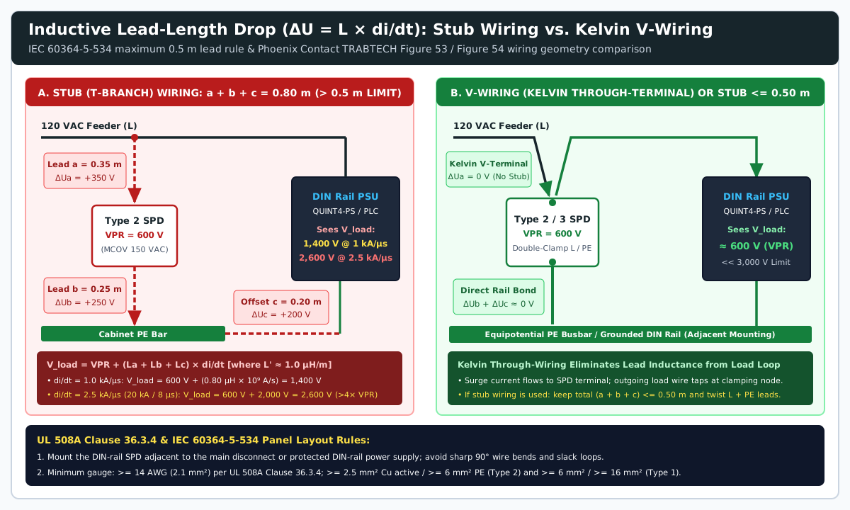
Rule of thumb: Keep the total parallel stub lead length a + b + c <= 0.50 m (500 mm) as required by IEC 60364-5-534 (and never above 1.0 m), avoid unnecessary bends per UL 508A Clause 36.3.4, and use >= 14 AWG (2.1 mm²) minimum conductor gauge (>= 6 mm² Cu active / >= 16 mm² Cu PE for Type 1; >= 2.5 mm² Cu active / >= 6 mm² Cu PE for Type 2) (UL SPD Guidelines, Phoenix Contact TRABTECH Basics 5131327). Whenever the SPD provides double-clamp through-terminals (such as PLT-SEC-T3-24-FM-UT or VAL-SEC), use V-wiring (Kelvin connection, Figure 54): route the incoming feeder wire directly to the SPD terminal and take the outgoing load wire to the din rail power supply from that same terminal (ΔUa = 0 V), while bonding the SPD PE foot directly to the grounded metallic DIN rail right beside the protected load (ΔUb + ΔUc ≈ 0 V) (Phoenix Contact TRABTECH Basics 5131327).
Takeaway: Size MCOV at or above 1.15× Un (evaluating full line-to-line voltage on ungrounded 480 V Delta panels), and use Kelvin V-wiring or <= 0.5 m leads so wire inductance (L × di/dt) does not multiply the installed clamping voltage.
Multi-Stage Energy Decoupling (10 m / 5 m Rule) and Signal-Line GDT + ESD Diode Coordination
Mounting a Type 1 spark gap, a Type 2 MOV, and a Type 3 suppressor side by side on the same DIN rail without verifying inter-stage decoupling causes premature failure of the downstream stages.
1. The 10 m and 5 m Power Cable Decoupling Rule vs. Combination Type 1+2 Arresters
As detailed in Phoenix Contact TRABTECH Handbook MNR 5131327 (Section 4.1, Figure 4.1-3 & Section 6.2.4), a passive Type 1 lightning current arrester built around an air or encapsulated spark gap requires an ignition voltage (usparkgap) of 2.5 kV to 4.0 kV before its arc channel ionizes and drops to a 20–30 V arc burning voltage. By contrast, a downstream Type 2 metal oxide varistor (MCOV = 275 V AC or 320 V AC) responds in < 25 ns and begins clamping the rail at 900 V to 1,000 V (Phoenix Contact TRABTECH Handbook, ABB Catalog 1SXU430100C0201).
If a passive Type 1 spark gap and a Type 2 MOV are wired within a few centimeters of each other inside the same enclosure (Lcable ≈ 0 µH), the fast Type 2 varistor clamps the bus voltage at ~1,000 V—well below the ~4.0 kV sparkover threshold of the Type 1 spark gap. Consequently, the Type 1 arrester never fires, and the Type 2 varistor is forced to absorb the full 10/350 µs (25 kA) lightning impulse until its thermal disconnect trips or the varistor disc shatters (Phoenix Contact TRABTECH Handbook).
To guarantee energy coordination between passive stages, IEC installation practice enforces minimum decoupling cable lengths (Phoenix Contact TRABTECH Handbook):
- Between Passive Type 1 (Spark Gap) and Type 2 (MOV): Maintain at least
10 m(33 ft) of feeder cable (Lcable≈10 µH). During a steep lightning front (di/dt), the inductive voltage drop along the10 mcable adds to the Type 2 clamping voltage (uType1=uType2+Lcable× di/dt), driving the upstream terminal aboveusparkgapso the Type 1 spark gap ignites and commutes the10/350 µsenergy to ground. - Between Type 2 (MOV) and Type 3 (Device Protector): Maintain at least
5 m(16.5 ft) of branch conductor (or10 m / 30 ftfrom the main service panel underUL 1449Type 3 rules) (UL SPD Guidelines, Phoenix Contact TRABTECH Handbook). - Inside a Single Control Cabinet (
0 mSeparation): Where the main disconnect and branch distribution reside inside the same enclosure without10 mof intervening feeder cable, specify an internally coordinated Type 1+2 combination arrester (such asPhoenix Contact FLASHTRAB FLT-SEC-T1+T2orFLT-CP) that integrates an active electronic ignition circuit to trigger the spark gap directly without external cable inductance (Phoenix Contact TRABTECH Basics 5131327, TRABTECH Handbook). Note that high-frequency load-side transients generated by inductive solenoids or heaters require local output clamping (RCsnubbers or load-side MOVs) as detailed in the solid-state relay zero-crossing vs. random turn-on guide.
2. Signal-Line Decoupling & the 2-Wire Pt100 RTD Resistance Error Trap
The same decoupling principle governs IEC 61643-21 measurement and control (MCR) surge modules and PCB-level RS-485 / 4–20 mA front-ends (Phoenix Contact TRABTECH Basics 5131327, Bourns/ADI AN-1161). In the Bourns AN-1161 Scheme 3 RS-485 architecture (2038-15-SM-RPLF 5 kA GDT + TBU-CA065-200-WH MOSFET current blocker + CDSOT23-SM712 esd protection diode), the secondary CDSOT23-SM712 diode clamps the initial 0.7–1.0 ns edge at +13.3 V / -7.5 V. Within < 1 µs, once surge current reaches the 200 mA trip threshold, the series TBU transitions to high impedance, forcing input voltage up to the ~500 V impulse sparkover of the 2038-15-SM-RPLF GDT so the gas tube fires and shunts the 8/20 µs surge current before the SM712 diode’s power limit is exceeded (Bourns/ADI AN-1161).
When applying passive resistor-decoupled DIN-rail signal SPDs to analog process instrumentation, watch the loop resistance budget (Phoenix Contact TRABTECH Basics 5131327, Section 6.4.1, Figure 84):
- 4–20 mA Current Loops: A two-stage signal SPD with
2 Ωseries decoupling resistors per wire (Rtotal=4 Ωloop resistance) produces a negligible voltage drop of4 Ω × 0.020 A = 0.080 V(80 mV), which is automatically compensated by the24 V DCloop transmitter’s compliance voltage. - 2-Wire Pt100 RTD Temperature Loops: A
Pt100platinum resistance thermometer has a nominal resistance of100.0 Ωat0 °Cand a temperature coefficient of roughly0.385 Ω/°C. Inserting a standard resistor-decoupled signal SPD with4 Ωof total series loop resistance adds a4%resistance error (+4.0 Ω), shifting the measured temperature reading by approximately+10 °C(10.4 °C) (Phoenix Contact TRABTECH Basics 5131327). ForPt100/Pt1000RTD circuits, specify inductor-decoupled (impedance-freeDC) RTD surge arresters or 3-/4-wire Kelvin-compensated RTD protection modules.
Takeaway: Provide >= 10 m of cable between passive Type 1 and Type 2 power SPDs (or use an active Type 1+2 combination module inside a single cabinet), and never place resistor-decoupled signal SPDs into 2-wire Pt100 RTD measurement loops.
UL 508A Supplement SB (SCCR), Backup Fuse Selectivity (F1/F2), and Remote Dry-Contact PLC Monitoring
Even when clamping voltages are properly stepped down, an improperly certified or unfused SPD can fail a UL 508A panel inspection or leave a machine operating with disconnected varistor cartridges after a surge event.
1. UL 508A Clause SB4.2.1 Panel SCCR Compliance (VZCA Listed vs. VZCA2 Recognized)
Under UL 508A Supplement SB (Clause SB4.2.1 and Table SA1.2), every power-circuit protective device connected to the main feeder or branch power circuits—including DIN-rail surge protection devices—must carry a marked Short-Circuit Current Rating (SCCR) equal to or greater than the available fault current and the control panel’s overall nameplate SCCR (typically 65 kA or 100 kA at 480 V AC) (UL SPD Guidelines, CITEL UL 508A SPD Guide).
Panel builders must distinguish between two UL product categories (UL SPD Guidelines, CITEL UL 508A SPD Guide):
- UL Listed Type 1, Type 2, and Type 3 SPDs (UL Category Code
VZCA): Fully tested self-contained assemblies (such asABB OVR T2series orPhoenix Contact FLT-SEC / VAL-SEC) marked with verifiedUL 1449SCCRratings up to200 kAwhen protected by the manufacturer’s specified upstream overcurrent device (for example,<= 100 A gG / Class Jfuse or<= 125 AB/C-curve circuit breaker per ABB Catalog 1SXU430100C0201). Installing aVZCAListed Type 1 or Type 2 SPD withSCCR = 200 kAandIn>=10 kA(20 kAfor service entrance) preserves a65 kAor100 kApanel nameplateSCCRautomatically. - UL Recognized Component Assemblies (Type 4CA / Type 5, UL Category Code
VZCA2): Incomplete component subassemblies that require specific external combinations or enclosures. UnderUL 508A, installing aVZCA2Type 4 or Type 5 SPD outside the conditions ofTable SA1.2triggers a mandatory custom “Procedure Described” UL engineering evaluation or derates the control panel’s overallSCCR(UL SPD Guidelines, CITEL UL 508A SPD Guide).
2. IEC Backup Fuse Selectivity (F1 vs. F2) and the 1 : 1.6 Ratio
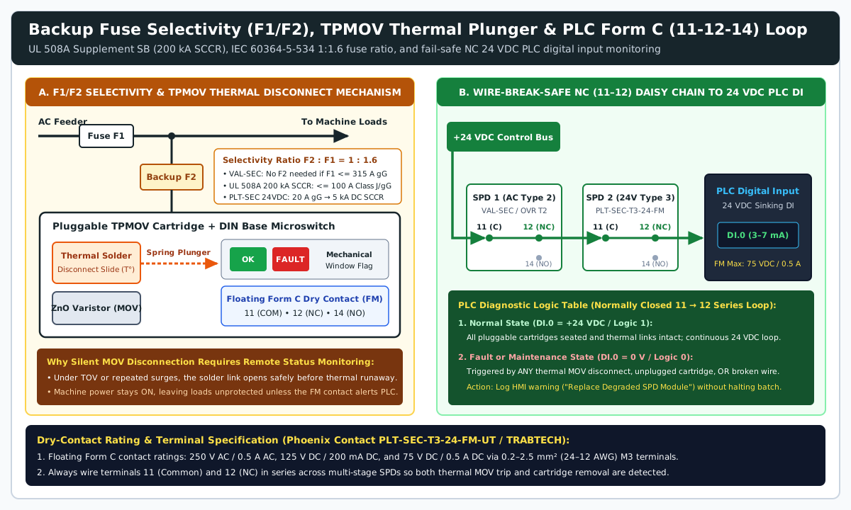
In IEC 60364-5-534 and Phoenix Contact TRABTECH Basics (Section 6.1.9–6.1.10, Figure 55), backup overcurrent protection for DIN-rail SPDs is engineered around the upstream main distribution fuse (F1) and an optional series SPD branch backup fuse (F2) (Phoenix Contact TRABTECH Basics 5131327):
- Fuse-Free Operation up to
F1 <= 315 A gG: High-capacity arresters such asPhoenix Contact FLT-SECandVAL-SECintegrate high-breaking-capacity thermal disconnects and withstand short-circuit currents without a separate series backup fuseF2whenever the upstream feeder fuseF1is<= 315 A gG(or<= 125 A gLfor standardVAL-MSvaristor bases) (Phoenix Contact TRABTECH Basics 5131327). - Selective Series Backup Fuse
F2(F2 : F1 = 1 : 1.6): When the upstream feeder fuseF1exceeds315 A gG, or when plant availability requires that a short-circuited SPD never trip the main machine feederF1, install a dedicated series backup fuseF2in the SPD branch sized by the selectivity ratioF2 : F1 = 1 : 1.6(Phoenix Contact TRABTECH Basics 5131327). For example, if the upstream machine feeder fuse isF1 = 200 A gG, selectF2 <= 200 / 1.6 = 125 A gG. - 24 V DC Type 3 Backup Fuse Rating: On the
Phoenix Contact PLT-SEC-T3-24-FM-UT(2907916), short-circuit current withstand isISCCR=0.25 kA DCwithout a backup fuse, increasing to5 kA DCwhen protected by a20 A gG / B-curvebackup fuse (and10 kA ACwith a25 A gG/B/Cbackup fuse in Kelvin through-wiring or32 Ain branch wiring) (PLT-SEC-T3-24-FM-UT Datasheet).
3. Thermal Disconnect Plunger & Fail-Safe Form C (11-12-14) PLC Alarm Wiring
When a metal oxide varistor reaches end-of-life due to cumulative surge absorption or sustained temporary overvoltage (TOV), its leakage current rises and heats the ZnO disc. Inside a Thermally Protected MOV (TPMOV such as Mersen Surge-Trap, ABB OVR T2, or Phoenix Contact VAL-SEC / PLT-SEC), a spring-loaded solder or wax thermal disconnect slide releases before the varistor reaches thermal runaway (Mersen TT-SPN6, Phoenix Contact TRABTECH Handbook).
Because the thermal disconnect opens the SPD branch cleanly without tripping the main feeder breaker, the machine continues operating with zero surge protection. Relying on a technician to open the cabinet door and inspect the local mechanical status window (Green = OK, Red = Fault) leaves the din rail power supply and PLC exposed to the next transient.
Industrial DIN-rail SPDs denoted with -FM (Phoenix Contact) or TS (ABB) couple the mechanical thermal plunger directly to a floating Form C (SPDT changeover) dry contact in the DIN-rail base (Phoenix Contact TRABTECH Handbook, ABB Catalog 1SXU430100C0201, PLT-SEC-T3-24-FM-UT Datasheet):
- Terminal
11: Common (COM) - Terminal
12: Normally Closed (NC— closed when all pluggable cartridges are thermally intact and fully seated in the base; opens when any thermal plunger trips or if a cartridge is unplugged) - Terminal
14: Normally Open (NO— closes on fault)
On the PLT-SEC-T3-24-FM-UT, this floating Form C switch is rated for 250 V AC / 0.5 A AC, 125 V DC / 200 mA DC, and 75 V DC / 0.5 A DC, accepting 0.2–2.5 mm² (24–12 AWG) conductors on M3 screw terminals (PLT-SEC-T3-24-FM-UT Datasheet). To integrate SPD health monitoring with the PLC input conditioning rules covered in the packaging machine sensor interface checklist, route +24 V DC control power in series through the Normally Closed (11 → 12) contacts of the AC Type 1/2 SPD, the 24 V DC Type 3 SPD, and any monitored signal SPDs into a 24 V DC sinking PLC digital input (DI). When all modules are healthy (DI = +24 V DC / Logic 1), the loop conducts 3–7 mA; if any varistor disconnects thermally, a cartridge vibrates loose, or the diagnostic wire breaks, the PLC input drops to 0 V (Logic 0) and logs a preventative maintenance alarm.
Takeaway: Specify UL Listed (VZCA) Type 1/2 SPDs with 200 kA SCCR to protect panel UL 508A nameplate ratings, size series backup fuses (F2) at <= F1 / 1.6, and daisy-chain the Normally Closed (11–12) dry contacts into a 24 V DC PLC digital input.
Control Panel SPD Specification & Commissioning Checklist
Use this seven-point verification table during schematic review and panel checkout to confirm complete din rail spd coordination:
| Check Item | Engineering Requirement & Standard Clause | Target Value / Pass Criterion |
|---|---|---|
| 1. Power Supply System & Grounding | Verify solidly grounded Wye vs. ungrounded or corner-grounded Delta (UL 508A Clauses 36.3.2 & 36.3.4) |
Slash-rated SPDs (480Y/277 V) used only on solidly grounded Wye sources; ungrounded 480 V Delta uses 550–660 V AC MCOV |
2. Continuous Voltage Margin (MCOV / Uc) |
MCOV >= 1.15× to 1.25× nominal voltage Un across every stage (ABB Catalog 1SXU430100C0201, PLT-SEC Datasheet) |
150 V AC (on 120 V), 320 V AC (on 277 V), 550 V AC (on 480 V Delta), 34 V DC (on 24.0–29.5 V DC din rail power supply bus) |
| 3. Clamping Margin vs. Equipment Immunity | Upstream VPR (6 kV / 3 kA) + lead drop must stay below downstream EN 61000-4-5 immunity (QUINT4-PS Datasheet) |
AC Type 2 VPR (600–1,000 V) < PSU AC input (3 kV L-N / 6 kV L-PE); DC Type 3 Up (<= 200 V) < PSU DC output (1 kV L+/L-) |
| 4. Lead Length & Kelvin V-Wiring | IEC 60364-5-534 stub lead rule (a + b + c) and UL 508A Clause 36.3.4 (>= 14 AWG / 2.1 mm²) |
Total stub lead length <= 0.50 m (500 mm) or direct Kelvin V-wiring through double-clamp SPD terminals (ΔUa = 0 V) |
| 5. Inter-Stage Energy Decoupling | Inductance decoupling between spark gap (Type 1), MOV (Type 2), and TVS/hybrid (Type 3) (TRABTECH Handbook) | >= 10 m cable between passive Type 1 & Type 2 (>= 5 m Type 2 to Type 3), or active Type 1+2 combination SPD inside single panel |
6. Panel SCCR & Backup Fuse (F1 / F2) |
UL 508A Clause SB4.2.1 (VZCA Listed) & IEC 1 : 1.6 backup fuse selectivity (UL SPD Guidelines, TRABTECH Basics) |
Marked SPD SCCR (200 kA) >= panel nameplate SCCR; series fuse F2 <= F1 / 1.6 when F1 > 315 A gG (20 A gG on PLT-SEC for 5 kA DC) |
| 7. Fieldbus ESD Stage & PLC Status Loop | IEC 61643-21 / AN-1161 GDT + TBU/R + esd protection diode; Form C (11–12–14) remote status loop (Bourns/ADI AN-1161) |
Impedance-free SPD on 2-wire Pt100 RTDs; 24 V DC wired in series through NC terminals (11 → 12) to PLC DI (Logic 1 = OK, 0 = Fault) |