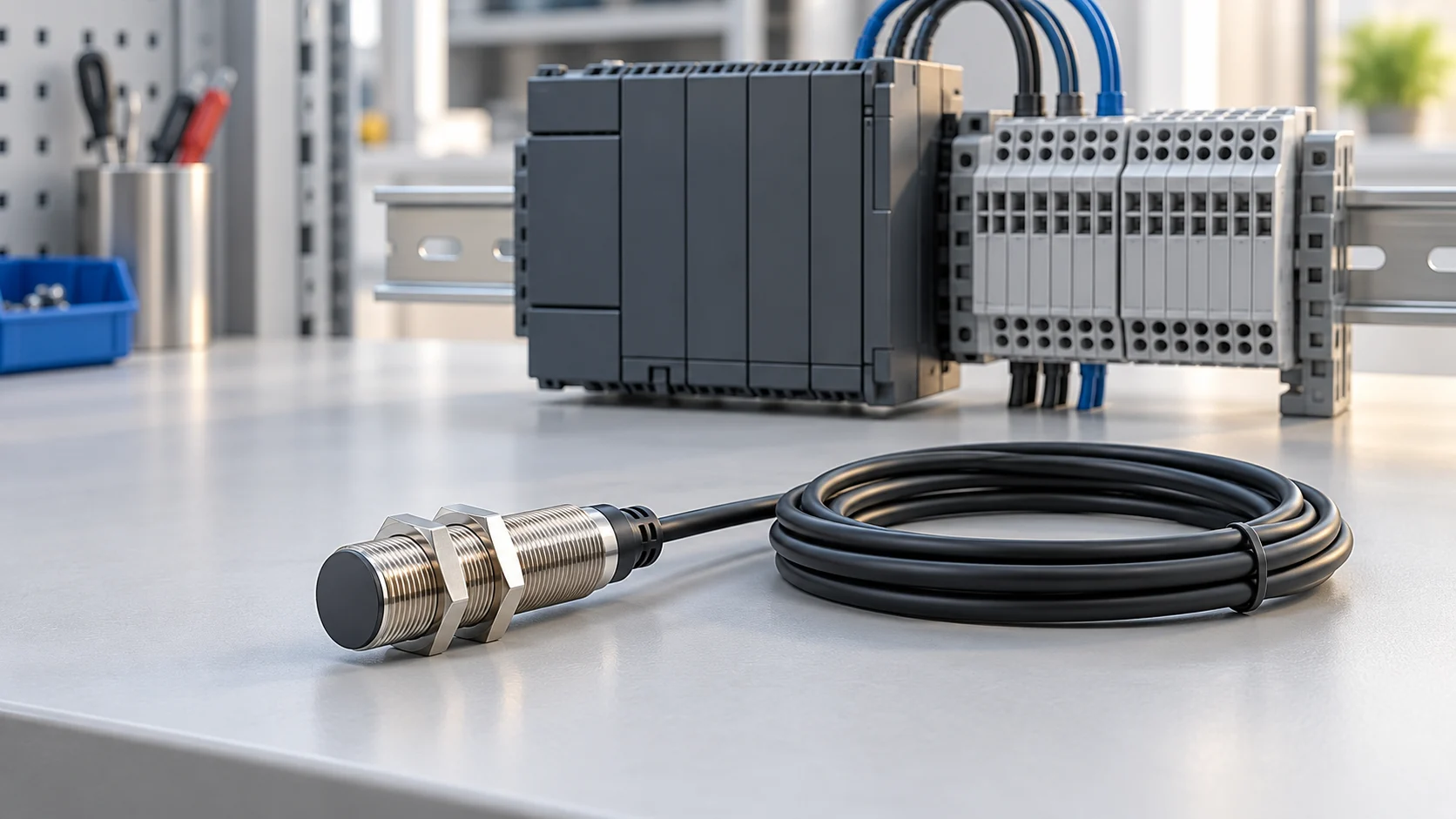
PNP vs NPN describes the direction of the sensor’s output current. On conventional 24V DC PLC inputs, a PNP proximity sensor sources current into a sinking input with COM at 0 V. An NPN sensor sinks current from a sourcing input with COM at +24 V. The sensor’s own supply polarity stays the same in both arrangements.
For proximity sensor wiring, make two decisions: match the current path, then check the electrical limits in both ON and OFF states. A correct polarity match can still fail because of residual voltage, leakage current or the minimum load of a two-wire sensor. This guide connects those checks to the wider industrial applications reading route.
| Comparison | PNP sensor output | NPN sensor output |
|---|---|---|
| Switching action | Connects the signal toward the positive supply | Connects the signal toward 0 V |
| Current function | Sources current | Sinks current |
| Matching PLC input circuit | Sinking input | Sourcing input |
| Conventional input COM | 0 V | +24 V |
| ON current path | +24 V → sensor → input → COM → 0 V | +24 V → COM → input → sensor → 0 V |
| First wiring check | Input must provide a return to 0 V | Input must provide current from +24 V |
Schneider Electric’s FAQ FA142566 and the CLICK Hardware Manual, chapter 3, describe these complementary current paths. Check whether a manufacturer’s phrase such as “PNP input” names the compatible sensor or the input circuit itself. The wiring diagram resolves that ambiguity.
How do you wire a three-wire PNP or NPN sensor?
Identify supply positive, supply return and output before connecting the PLC common. Brown, blue and black are common assignments for +V, 0 V and output, respectively, but use the actual sensor and cordset diagram to identify conductors and connector pins.
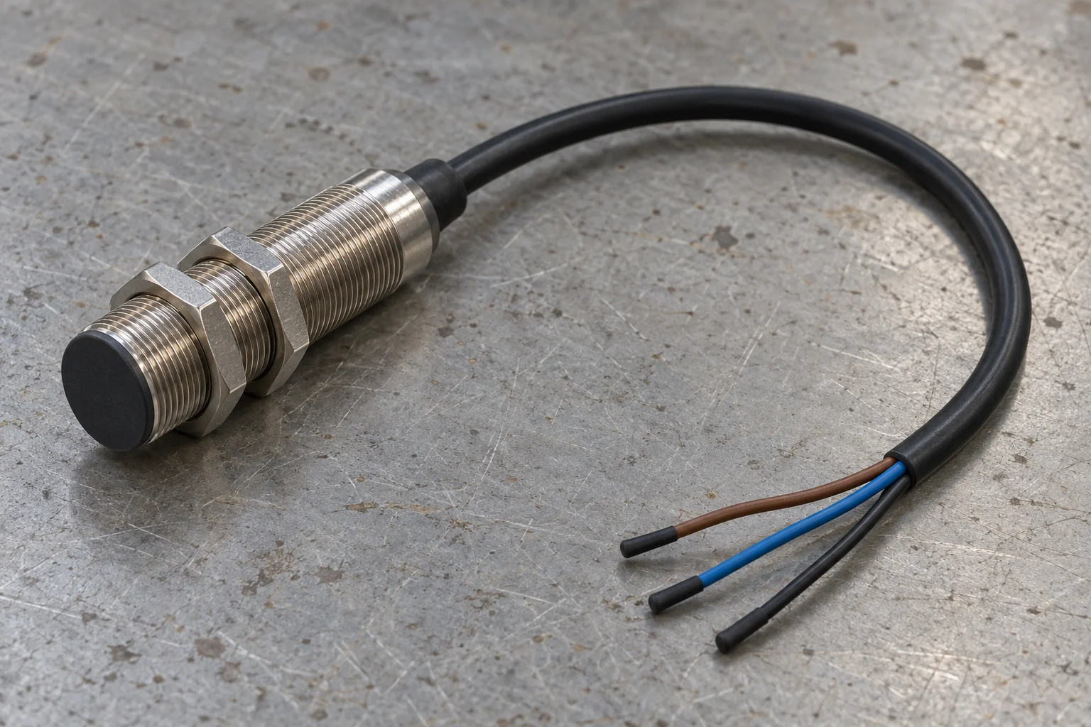
| Terminal function | PNP with sinking input | NPN with sourcing input |
|---|---|---|
| Sensor +V | Positive DC supply within sensor rating | Positive DC supply within sensor rating |
| Sensor 0 V | Supply return | Supply return |
| Sensor output | Selected PLC input terminal | Selected PLC input terminal |
| Associated PLC input COM | Supply 0 V | Supply +24 V |
The following diagrams show the ON state. Arrows follow conventional current through the switched load path. Sensor supply connections are also shown; the input block represents the module’s receiving circuitry.
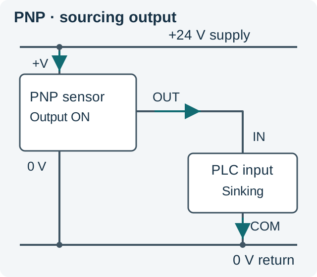
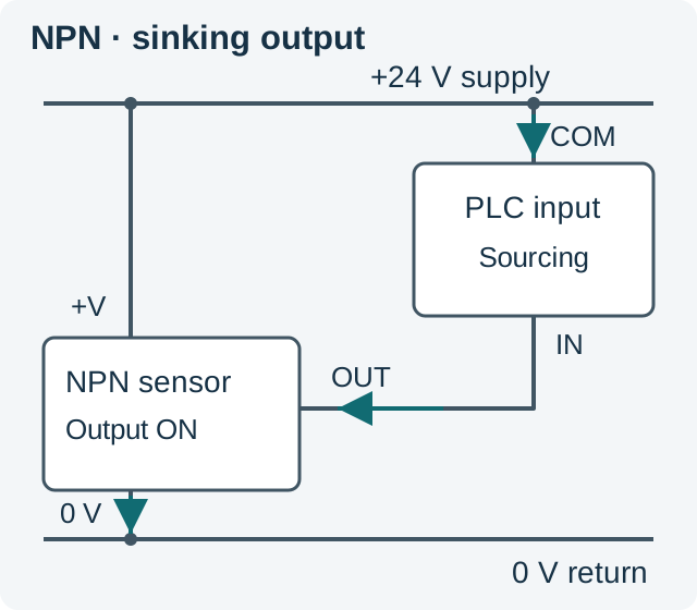
Check the whole common group
A common terminal can serve several inputs. Moving it changes the current path for every channel in that group. A documented sink/source module can accept either arrangement; a fixed-polarity module must keep its specified common connection.
For example, the AutomationDirect C0-16ND3 has four isolated commons, each serving four inputs. The CLICK wiring manual requires a consistent current orientation within each common group. If one group is wired for PNP sensors, an NPN replacement on one of its channels cannot be accommodated simply by moving that group’s common while leaving the other sensors unchanged.

Check ON voltage and OFF leakage separately
Compatibility requires enough voltage and current to turn the input ON, and sufficiently little voltage and current to guarantee OFF. Two-wire sensors make both checks especially important because their electronics draw current through the load.
The table below pairs the C0-16ND3 input specifications with the DC two-wire E2E-X…D… ratings in Omron’s E2E datasheet. It gives the limits needed for a compatibility calculation.
| Parameter | CLICK C0-16ND3 input | Omron E2E DC two-wire ratings |
|---|---|---|
| Operating range | Input: 21.6–26.4 V DC | Sensor: 10–30 V DC; nominal 12–24 V DC |
| ON voltage / sensor drop | Input ON level: >19 V DC | Residual voltage: ≤3 V at 100 mA load, 2 m cable |
| ON current / load range | Minimum ON current: 3.5 mA | Load current: 3–100 mA |
| OFF limits / leakage | OFF level: <7 V DC; maximum OFF current: 0.5 mA | Leakage current: ≤0.8 mA |
| Input consumption | Typical 4 mA at 24 V; maximum 5 mA at 26.4 V | Use the load-current range above |
| Input impedance | 6.8 kΩ at 24 V | — |
Source locations: CLICK Hardware Manual, chapter 2, C0-16ND3 table, page 2–119; Omron E2E datasheet CSM_E2E_DS_E_13_6, DC two-wire ratings, page 7.
The OFF-current comparison is immediate: the sensor’s 0.8 mA maximum leakage exceeds the input’s 0.5 mA maximum OFF current. Those ratings do not establish guaranteed OFF compatibility for a direct connection. An individual combination may switch, but selection must cover the specified limits.
For ON voltage, use:
Vinput,on = Vsupply − Vsensor,on − Vcable
Using the stated 3 V residual drop for screening, a nominal 24 V supply leaves 21 V before cable loss. At the input range’s 21.6 V lower endpoint, it leaves 18.6 V, below the input’s >19 V ON requirement. Apply the sensor’s residual-voltage characteristic at the actual load; the quoted 3 V specification carries a 100 mA, 2 m cable condition.
This produces two separate design checks: divert excess OFF leakage if needed, and retain enough ON-voltage headroom at the lowest supply voltage. A bleeder can address the first issue while increasing the sensor’s ON load; it cannot recover voltage lost in the sensor or cable.
The input’s 6.8 kΩ figure is specified at 24 V. Its semiconductor input circuit need not behave as a linear resistor near the OFF threshold, so retain the separate 0.5 mA OFF-current requirement rather than replacing it with a single V/R calculation.
Where does a two-wire sensor’s bleeder resistor go?
Connect a bleeder in parallel with the PLC input, between the input terminal and its associated common. It gives OFF leakage another path and adds load current when the sensor conducts. Omron’s CJ2 CPU Unit Hardware User’s Manual W472-E1-16, pages 5–36 and 5–37, sets out the voltage, load-current and leakage checks.
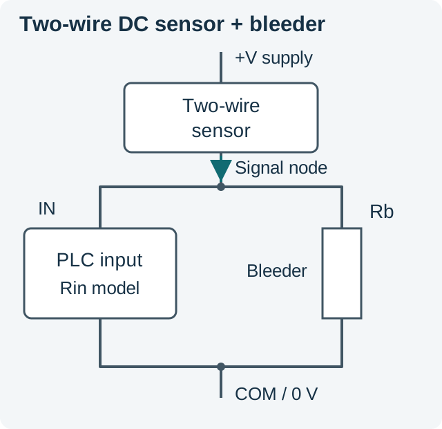
Calculate resistance from the input model
Let Ileak be the maximum sensor leakage, Rin the applicable input resistance, Rb the bleeder and Voff the permissible OFF voltage. For a resistive input model:
Vinput,off = Ileak × (Rin ∥ Rb)
The parallel resistance is RinRb / (Rin + Rb). Omron’s limiting resistance expression is:
Rb ≤ (Rin × Voff) / (Ileak × Rin − Voff)
Use volts, amperes and ohms. This bound applies when the denominator is positive. If it is zero or negative, the simplified voltage calculation already meets the limit without a bleeder; check OFF current separately. Where an input specifies a strict “less than” threshold, select below the limiting result with allowance for component and operating tolerances.
A conservative voltage-only bound, ignoring current accepted by the PLC input, is Rb < Voff / Ileak. With the named 7 V and 0.8 mA limits, this gives Rb < 8.75 kΩ. It is only the voltage bound: the selected circuit must also keep actual input current within 0.5 mA and meet all ON-state requirements. Use the input’s low-voltage characteristic to check that operating point.
Check ON load and resistor heating
Calculate the sensor’s total ON current as the input current plus the bleeder current:
Isensor,on = Iinput,on + Vbleeder,on / Rb
Keep that sum within the sensor’s minimum and maximum load ratings throughout the supply range. For the E2E ratings above, the relevant load band is 3–100 mA. A smaller resistor diverts more leakage but increases current and heat.
Resistor dissipation is Pb = Vbleeder,on² / Rb. The W472 manual uses a fourfold allowable power margin. For maximum heating, use the highest voltage that can actually appear across the bleeder and the resistance tolerance that produces the highest dissipation, then apply the resistor’s temperature derating. Subtracting a sensor’s maximum voltage drop would underestimate the maximum voltage across the resistor. Verify the installed supply maximum and enclosure conditions before choosing its power rating.
Can an NPN sensor work with a fixed sinking PLC input?
An NPN output and a fixed sinking input both need another element to supply the loop current. The practical choices are a compatible sensor, documented input reconfiguration or a specified signal converter.
| Approach | Condition to verify | Main consequence |
|---|---|---|
| Use a PNP sensor | Detection task, supply, NO/NC, connector and electrical limits match | Provides the sourcing output the input needs |
| Reconfigure a sink/source input group | Module permits it and every channel in the group is compatible | Changes the common arrangement for the whole group |
| Use a PNP/NPN converter | Input/output thresholds, current, voltage drop, leakage, response and startup state fit | Adds a device whose behavior must be included in the interface check |
| Add a pull-up circuit | Both logic states, sensor sink current and resistor dissipation are calculated | Inverts the electrical logic and adds continuous load when pulled low |
AutomationDirect’s sensor signal converter range documents polarity-conversion products. If electrical isolation is required, check the chosen converter’s explicit isolation rating as well as its conversion function. For optical interfaces, the optocoupler current-transfer and timing guide explains additional current, temperature and timing constraints.
A pull-up connects from +24 V to the shared sensor-output/input node, with the sinking input’s COM at 0 V. When the NPN transistor is OFF, the resistor can supply input current and raise the node. When the transistor is ON, it pulls the node low. Thus the PLC electrical state is inverted relative to transistor conduction.
At the high-state operating point, current balance requires:
(Vsupply − Vnode) / Rpull = Iinput(Vnode) + Isensor,leak
Use the actual input I–V characteristic to establish the high state. At the low state, verify the transistor can sink the pull-up current while keeping the node below the input’s OFF limits, and check resistor heating. A pull-up is a different circuit from a two-wire bleeder. Software inversion also changes neither wire-fault behavior nor the available diagnostics.
Does NO or NC make either polarity fail-safe?
NO/NC describes the relationship between target detection and output conduction; PNP/NPN describes current direction. For the Omron E2E table above, D1 variants are NO and D2 variants are NC. Follow the timing chart for the exact variant.
In a conventional NO arrangement, target detection turns the output ON. In an NC arrangement, target detection turns it OFF. An NC circuit with current flowing in its expected healthy state can reveal some open-circuit faults when that current disappears. The controller must interpret and respond to that change appropriately.
| Wiring event | Conventional PNP / sinking input | Conventional NPN / sourcing input |
|---|---|---|
| Signal conductor opens | Intended input-current loop is interrupted | Intended input-current loop is interrupted |
| Signal shorts to frame, with frame bonded to supply 0 V | Input node is pulled low; sensor output protection may operate | A return path to 0 V can make the input active |
| Different grounding or a fault on another conductor | Evaluate the actual fault-current path | Evaluate the actual fault-current path |
Omron FAQ02285 explains the importance of the grounded supply pole when evaluating an output-to-frame fault. The second row assumes a 0 V/frame bond; the result changes with the grounding arrangement and fault location.
Whether an input state stops, alarms or permits operation depends on the control logic and diagnostics. Use an independently engineered safety system for personnel protection. Ordinary proximity sensing and NC selection alone do not establish a safety function; Omron’s proximity-sensor precautions make that distinction explicit.
Troubleshoot the circuit in this order
Trace the receiving input’s complete loop before changing parts or adding resistors. Isolate machinery under site procedures before rewiring. Qualified personnel should perform energized measurements using the equipment’s approved procedures.
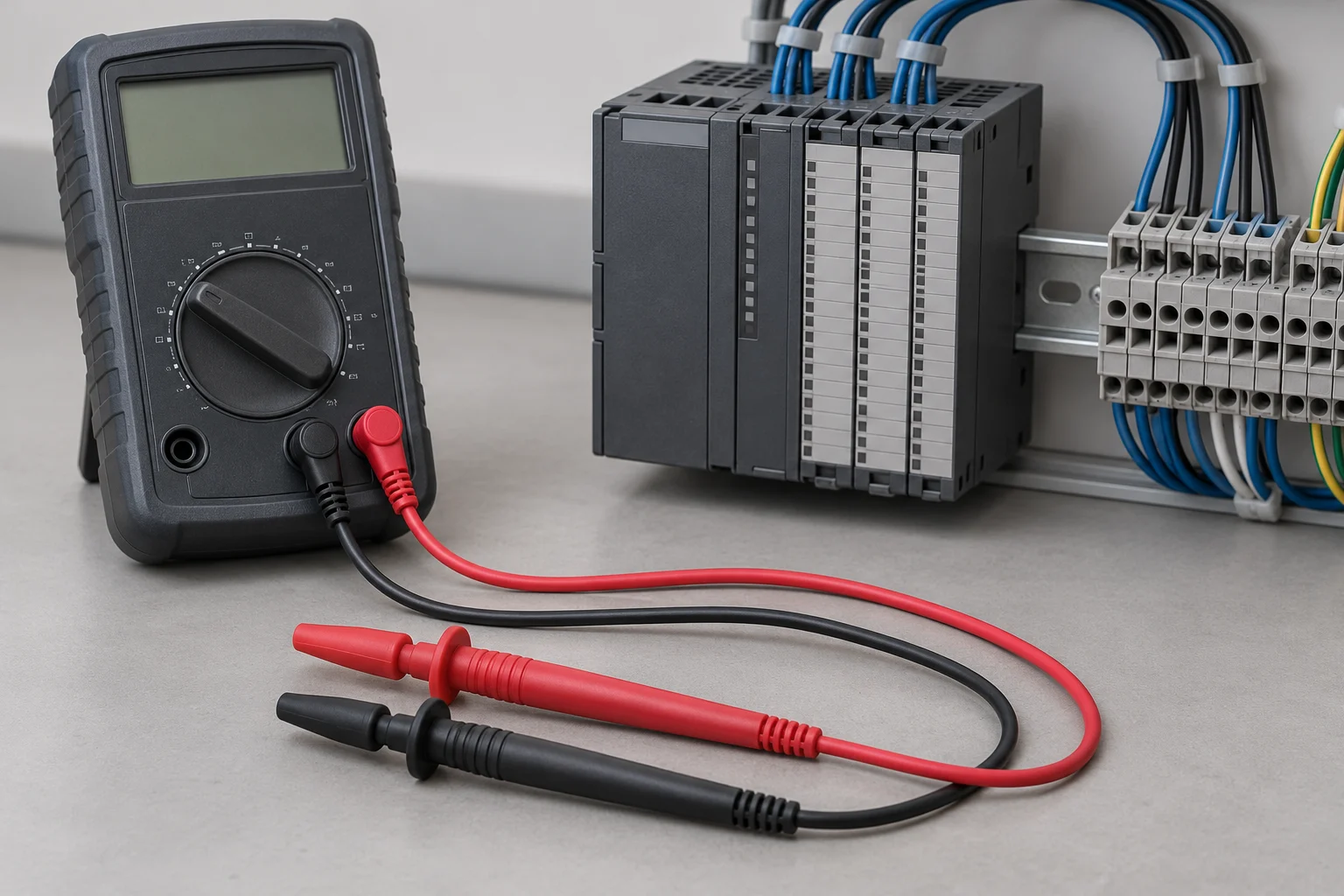
- Read both part numbers and diagrams. Identify PNP/NPN, NO/NC, two-wire/three-wire, supply range and the exact input channel. Confirm cable pin assignments.
- Trace supply and common. Check the sensor supply pair, input return path and every channel sharing the common. Follow the module diagram for fixed or configurable polarity.
- Check the voltage across the input circuit. For PNP, the input terminal is positive relative to its 0 V common when ON. For NPN, the +24 V common is positive relative to the low signal terminal. Preserve meter polarity when interpreting readings and compare with the documented voltage limits.
- Check OFF leakage and ON load. If a two-wire sensor leaves an input active or an indicator faintly lit, compare leakage, OFF thresholds, minimum load and residual voltage. Calculate any bleeder across the full operating range.
- Check the controller interpretation. Confirm channel address, raw input state, filters and program logic. An indicator LED alone cannot establish the program state. The W472 manual also identifies sensor startup current as a possible cause of a false input, so use the actual device’s stabilization timing when checking power-up behavior.
Before closing the job, retain this matching checklist with the equipment documentation:
| Check | Record for the installed circuit |
|---|---|
| Output and logic | Sensor part number, PNP/NPN, NO/NC and timing diagram |
| Supply and conductors | Allowed voltage range, actual supply extremes, cable/connector assignments |
| Input topology | Module part number, channel, common group and common potential |
| ON limits | Lowest input voltage after losses; input current and total sensor load |
| OFF limits | Maximum leakage, resulting input voltage and input current |
| Added interface parts | Converter characteristics or resistor calculation, tolerance and thermal rating |
| Operation | Target-present/absent states, startup behavior and relevant fault response |
Use the packaging-machine sensor interface checklist to carry these electrical results into the broader sensor/controller documentation handoff.
Technical references
- Schneider Electric, FAQ FA142566: three-wire PNP/NPN sensor connections and NO/NC distinction.
- AutomationDirect, CLICK Hardware User Manual, edition 6, revision Q: chapter 3, pages 3–31 and 3–47, current paths and sensor wiring; chapter 2, page 2–119, C0-16ND3 input specifications.
- Omron, E2E Proximity Sensor Datasheet, CSM_E2E_DS_E_13_6: page 7, DC two-wire ratings; pages 13 and 17, timing and PLC connection conditions.
- Omron, CJ2 CPU Unit Hardware User’s Manual, W472-E1-16, pages 5–36 and 5–37: two-wire compatibility, bleeder equations, power margin and startup behavior.
- Omron, Proximity Sensors Safety Precautions, leakage-current and safety-use sections; FAQ02285, grounded-supply and output-to-frame fault behavior.
- AutomationDirect, Sensor Signal Converters, polarity-conversion product overview.