A logic input that still switches on the bench can fail after the optocoupler’s current-transfer ratio falls, and a common-mode number copied from a 10 V test will not describe a 1,200 V edge. Isolation design starts with CTR at the real LED current and temperature, then reads CMTI only beside the voltage used to measure it.
Optocoupler isolation for high-speed logic is an LED, a detector, and a stated CTR, plus a common-mode test that names its voltage. Vishay defines CTR as collector current divided by forward current, times 100%. CTR degradation over time comes primarily from the emitter chip: radiation power falls under high ambient temperature and high forward current. Broadcom’s 6N137 family is the high-speed logic example here, specified as suitable for high-speed logic interfacing, with 10 MBd typical. Texas Instruments’ ISO7741 is the logic-input digital isolator in the same comparison. Its CMTI is not a drop-in upgrade for the LED input.
| Input or item | Published value or condition | Dominant failure mode if the row is ignored |
|---|---|---|
| CTR definition | Ic / If × 100% | The gain the circuit actually uses |
| Vishay 83741 starting point | Typical 100% at If = 10 mA | The bin before temperature and aging |
| Temperature, −20 °C to +60 °C | +12% to −17% on that example | The cold-to-hot swing; the loss side is 0.83 |
| Ten-year degradation allowance | About 20% further reduction | Vishay’s service-life factor in that example, 0.80 |
| Tolerance allowance | About −25% | The remaining factor, 0.75, gives 49.8% |
| 6N137 |CMH| | 1,000 V/µs min, 10,000 typical, |VCM| = 10 V | High-speed logic immunity at a low test voltage |
| HCPL-2611 |CMH| | 15,000 V/µs min, 25,000 typical, |VCM| = 1 kV | A shielded part in the same family, different test voltage |
| ISO7741 CMTI, 5 V table | 85 kV/µs min, 100 typical, VCM = 1,200 V | Logic-input isolator, 5 V ±10% supplies |
CTR after temperature, aging, and tolerance
In the Vishay 83741 phototransistor-to-emitter-resistor example, the designer starts from a typical CTR of 100% at If = 10 mA. From −20 °C to +60 °C the CTR change is between +12% and −17%. The −17% side is the one that starves the output, so the temperature factor is 0.83. A ten-year service life adds about 20% further CTR reduction for degradation, factor 0.80. A further tolerance allowance of about −25% is factor 0.75.
CTRmin = 100% × 0.83 × 0.80 × 0.75 = 49.8%.
The circuit is then designed for that 49.8%, not for the 100% bin. Supply in the example is 5 V. The same document’s saturated-CTR walkthrough for a different coupler uses a normalized factor and lands near 42.6% after a similar 20% aging term and −25% tolerance. Copy the factor from the curve for the exact series. Do not reuse 49.8% as a universal floor.
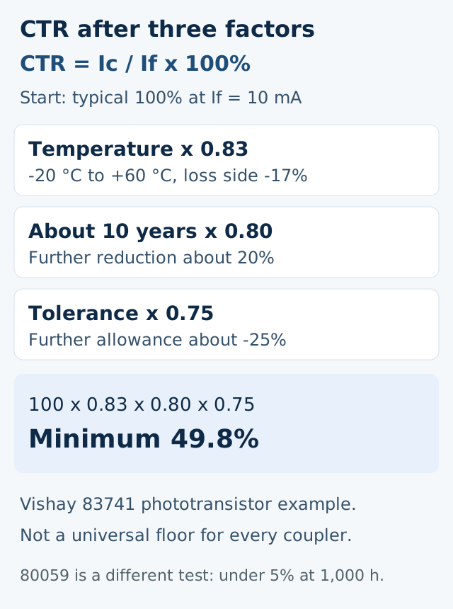
Vishay’s general description, document 80059, is a different statement and should stay separate. There, optocouplers run at 1 to 30 mA. In that range, at an average temperature of 40 °C, degradation is less than 5% after 1,000 h. Lifetime is given as 100,000 h, with CTR still at or above 50% of the 0 h value. Less than 5% at 1,000 h and 40 °C does not replace the 20% ten-year allowance in 83741. The allowances answer different questions: one is a stated life-test band, the other is a design stack for a 10-year interface.
If the LED current or the ambient temperature is outside the condition printed next to the CTR curve, the 0.83 and 0.80 factors stop applying. Vishay’s normalized-curve note says CTR also moves with collector-emitter voltage and with forward current, and the curves are scaled to a nominal point, often 25 °C and the coupler’s stated If. Read the curve at the If the resistor will actually set.
If the design needs the output saturated, use the saturated CTR curve, not the linear 100% example. The 49.8% walkthrough is the emitter-resistor case. A logic-low interface that must pull down against a stated load resistor needs the CTR and the If that the datasheet pairs with that load.
High-speed logic CMTI, each number with its voltage
The 6N137, HCPL-2601/2611, and the related SO-8 and widebody parts are optically coupled gates: a GaAsP LED and a high-gain photodetector, with an enable on the single-channel parts. The output is an open-collector Schottky-clamped transistor. Broadcom prints high speed as 10 MBd typical, and AC/DC parameters over −40 °C to +85 °C.
On the logic-high common-mode row, at VCC = 5 V and TA = 25 °C, with IF = 0 mA, VO remaining above 2.0 V, and RL = 350 Ω:
| Device | Minimum |CMH| | Typical | Common-mode voltage in that row |
|---|---|---|---|
| 6N137 | 1,000 V/µs | 10,000 V/µs | |VCM| = 10 V |
| HCPL-2601 / 2631, HCPL-0601 / 0631, HCNW2601 | 10,000 V/µs | 15,000 V/µs | |VCM| = 1 kV |
| HCPL-2611 / 4661, HCPL-0611 / 0661, HCNW2611 | 15,000 V/µs | 25,000 V/µs | |VCM| = 1 kV |
The logic-low row uses IF = 7.5 mA and VO remaining below 0.8 V. The 6N137 minimum there is again 1,000 V/µs at |VCM| = 10 V. The selection guide repeats the split: 6N137 is 1,000 V/µs at 10 V, while HCPL-2611 is 15,000 V/µs at 1,000 V. A footnote on a different row, the HCPL-261N line, says 15 kV/µs at VCM = 1 kV can be reached with a Broadcom application circuit. That footnote is not the 6N137 minimum.
A 0.1 µF bypass from pin 5 to pin 8, placed close to the package, is required. If the enable pin is unused, tying it to VCC improves CMR on the single-channel parts.
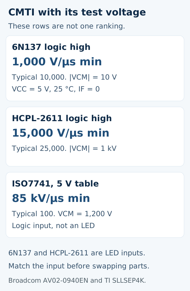
ISO7741, in SLLSEP4K Rev. K revised August 2026, is a quad-channel digital isolator. The feature list prints ±100 kV/µs typical CMTI. The 5 V electrical table, VCC1 = VCC2 = 5 V ±10%, lists CMTI minimum 85 kV/µs and typical 100 kV/µs, with VI at VCCI or 0 V and VCM = 1,200 V. The 3.3 V and 2.5 V tables in the same file also list 85 kV/µs minimum. Data rate on the feature list is 100 Mbps. Propagation delay is 10.7 ns typical at 5 V supplies. Default output is high for ISO774x and low for the F suffix.
If a board edge is a 1 kV-class common-mode transient, the 6N137’s 1,000 V/µs rating does not cover it, because that minimum was taken at 10 V. The part that carries 15,000 V/µs in this family is the HCPL-2611 class, and its row is at |VCM| = 1 kV. ISO7741’s 85 kV/µs minimum is at 1,200 V and at a logic input.
If the signal into the isolator is an LED current rather than a CMOS logic level, an ISO7741 is the wrong input circuit. The 6N137 input is the LED forward current, with a low-input-current capability of 5 mA printed in the feature list. ISO7741’s input thresholds are fractions of VCCI. Swapping packages without changing the driver leaves the LED current with nowhere to go.
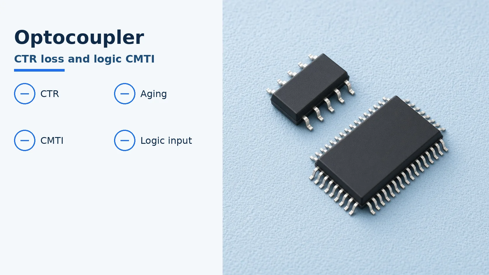
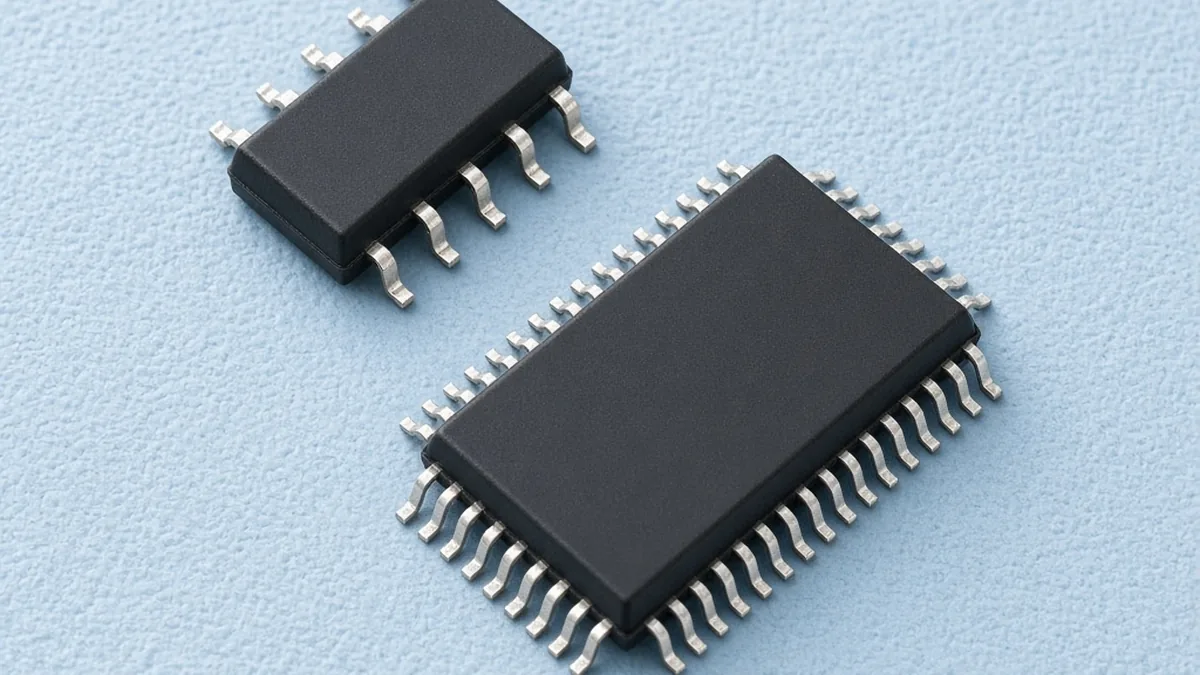
The photograph below is two unmarked packages on a mat. It shows the scale difference between a small-outline part and a wider multi-pin package. It does not identify a 6N137 or an ISO7741, and it shows no isolation slot.
Where these numbers stop
CTR bins, temperature factors, and CMTI rows belong to the part number and the test condition in the row. A 49.8% floor from a 10 mA, −20 °C to +60 °C phototransistor example is not the floor for a 6N137, which is specified as a logic gate rather than by that CTR stack. Isolation voltage is also per package option: the 6N137 family file distinguishes 3,750 Vrms and 5,000 Vrms recognitions by option, and ISO7741’s feature list goes up to 5,000 Vrms. Copy the option that is actually on the reel.
An SSR output switch often hides a photocoupler on its input. The load-side choice, zero-cross versus an SSR without that function, is a different limit and is set out in the solid-state relay turn-on guide. ISO7741’s own description of keeping noise off RS-485, RS-232, and CAN belongs with the interface comparison, which separates the electrical port from the application data. Part identity and the condition columns stay in the ordering-code record and the datasheet condition checklist. This page is part of the components route.
Method and sources
CTR arithmetic is Vishay document 83741, accessed 19 October 2026. The 1,000 h / 40 °C statement is Vishay document 80059. CMTI rows for the 6N137 family are Broadcom AV02-0940EN. ISO7741 figures are Texas Instruments SLLSEP4K Rev. K, the 5 V electrical characteristics table and the feature list. No minimum was compared across those rows without its common-mode voltage.