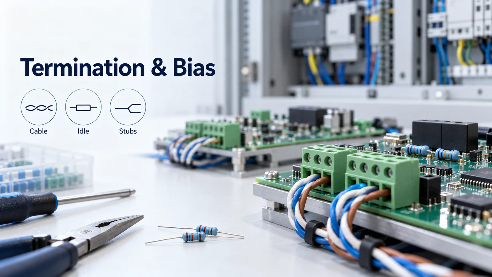
For parallel termination on a shared pair, each end of the link has a termination resistor equal to the cable characteristic impedance. There should be no more than two terminating resistors in the network.
Start with the cable ends, then work through idle bias and branch timing. Use the checklist below to organize your bus review.
Match the cable and terminate its ends
In a half-duplex configuration, both ends of the cable must be terminated. You should activate the termination resistors only at the end nodes.
Trace the cable route and mark the end nodes before reviewing the termination switches.
Twisted-pair characteristic impedance typically ranges from 100Ω to 150Ω. The default termination value in the nominal twisted-pair discussion is 120Ω. An impedance mismatch creates reflections at the network ends.
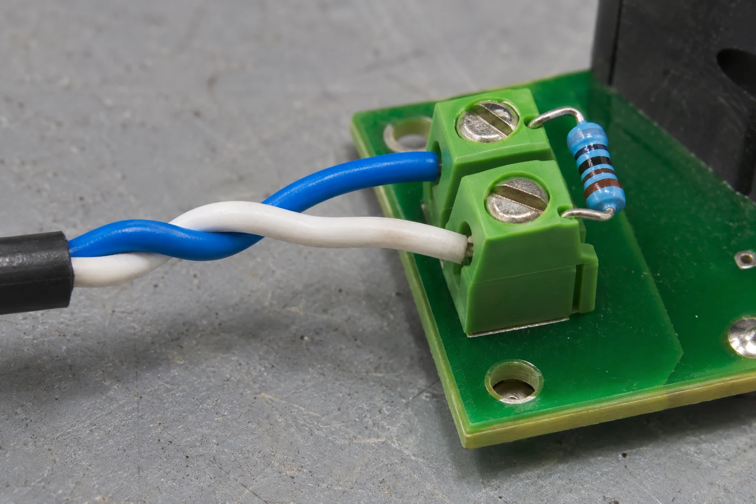
A 60Ω termination load results from 120Ω at each end of the bus. Termination networks add a parallel driver load and increase steady-state load currents. In the example with termination enabled at every node, four termination resistors in parallel excessively load the driver.
Record each enabled termination alongside its position on your cable sketch.
Review timing before omitting termination
A cable is not seen as a transmission line if the signal rise time is more than four times the propagation delay of the cable.
Use driver rise time and cable propagation delay as the inputs to this check.
A possible unterminated case occurs when the two-way loop time of the network is much shorter than a single bit time (~<0.1×tBIT).
For the settling check, record the loop time and bit time separately. Keep the rise-time check beside it in your review.
Separate idle behavior from termination placement
An idle bus condition occurs when no bus driver is actively driving. For a conventional receiver on an undriven bus, an undefined idle receiver output can cause random UART data, false start bits, false interrupts, and framing errors.
Pull-up and pull-down resistors at one bus position can solve the undefined idle-output problem. A typical RS-485 transceiver has a differential input threshold voltage of ±200 mV.
Review the receiver threshold and the idle target together.
Idle differential bus voltage must exceed the maximum input threshold to force all receiver outputs high. The bias target includes a noise margin: VAB = VIT-MAX + VNoise.
Size external bias with the complete load
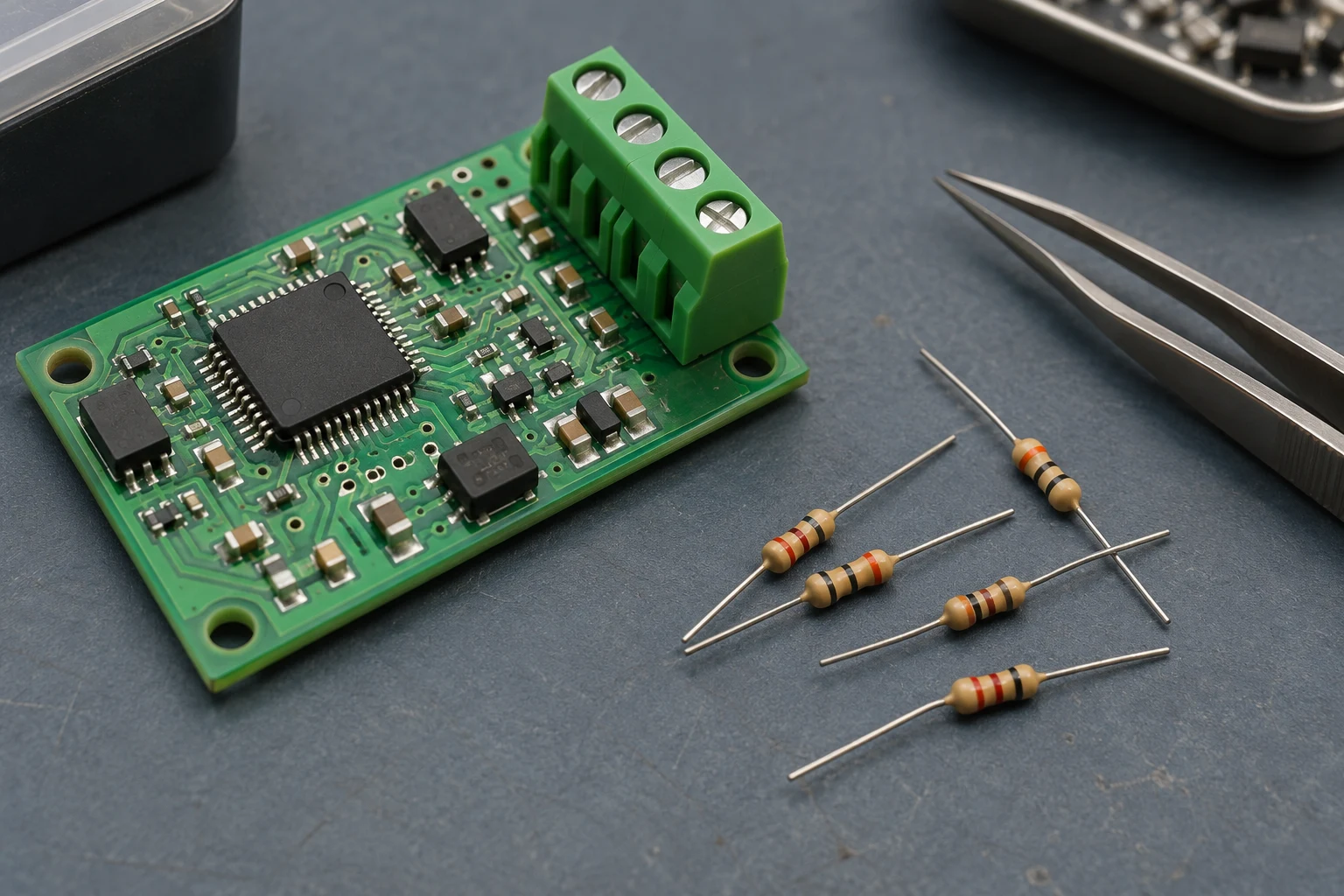
Calculate bias resistors using supply voltage and bus load, including terminations and receiver impedances. Adding transceivers and fail-safe circuits increases required bus load current.
Keep the common-mode load check explicit
One unit load represents a minimum common-mode resistance of around 12kΩ between each signal conductor and ground. Thus, 32 parallel unit loads give a minimum common-mode resistance of RCM = 375Ω. The parallel combination of bias resistance and equivalent receiver resistance must satisfy RB||REQ ≥ RCM.
Record the receiver load and the bias resistance together for this check.
Published single-end bias example
At the biased end, the parallel combination of the two series bias resistors and the termination must match cable impedance: Z0 = 2RB||RT2.
Use the following condition set when reviewing the example:
- ISL8487E is a 1/8 UL transceiver in the calculation example.
- The ISL8487E calculation uses a minimum supply of VS = 4.75V.
- The example assumes a 100mV noise margin.
- The example uses an idle bus target of VAB = 300mV.
- The single-end example sets RT1 = Z0 = 120Ω.
- The single-end example chooses RB = 470Ω.
- The single-end example chooses RT2 = 138Ω.
Keep those inputs and resistor selections together in the calculation record. For your own bus, repeat the supply-and-load calculation using the installed receivers and terminations.
Check the receiver’s fail-safe conditions
If all connected transceivers have true fail-safe features, receiver output is defined during idle.
List each receiver and check its documented idle, open-input, and short-circuit behavior.
ADM3095E provides a logic-high receiver output for idle, open, and short-circuit conditions across ± 25 V input common-mode range.
Use that condition list when reading the selected receiver’s data sheet.
Set stub length from driver rise time
A stub electrical length should be shorter than 1/10 of driver output rise time.
For the physical-length check, use the published guideline:
The maximum physical stub length guideline is L(STUB) ≤ 0.1 × tr × v × c. tr is the 10/90 rise time of the driver. v is the cable or trace signal velocity as a factor of c.
Record the driver rise time and cable velocity beside each branch in the cable sketch.
Drivers with long rise times are well suited to applications requiring long stubs. Loop the main cable to the device instead of adding a long branch stub.
Consider the tradeoff in AC termination
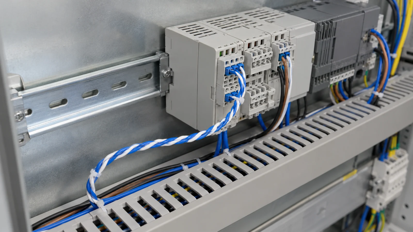
For AC termination, a resistor and capacitor can be placed in series across the bus between A and B. A series capacitor makes steady-state termination current go to zero. The RC time constant slows differential edges and limits maximum network data rate.
Review the current and edge-timing requirements together before selecting this topology.
Bus-review checklist
Complete these records before closing the wiring review:
- Cable sketch: mark the end nodes and each enabled termination.
- Impedance check: enter the cable characteristic impedance and end-resistor values.
- Idle check: list the receiver conditions, threshold, target, and noise allowance.
- Bias calculation: record supply voltage, terminations, receiver impedances, and common-mode loading.
- Stub check: record driver rise time, cable velocity, and the branch route.
Continue with the embedded-control guides or the industrial-interface comparison for your next design review.
Sources
- Analog Devices — AN-960 RS-485/RS-422 Circuit Implementation Guide.
- Texas Instruments — RS-485 Basics: When Termination Is Necessary, and How to Do It Properly.
- Texas Instruments — AN-1057 Ten Ways to Bulletproof RS-485 Interfaces.
- Renesas — AN1986 External Fail-Safe Biasing of RS-485 Networks.
- Analog Devices — AN-1399 Enhanced RS-485 Performance.
- Texas Instruments — The RS-485 Design Guide.
- Texas Instruments — THVD1450 data sheet.