Deploying an unmanaged industrial ethernet switch in a multi-drive automation line floods real-time multicast I/O packets across every port and causes immediate broadcast-storm failure and downtime if two ports are looped. Relying on slow spanning-tree recovery or a single unmonitored power feed causes PLC watchdog faults, dropped drive connections, and unplanned machine stops.
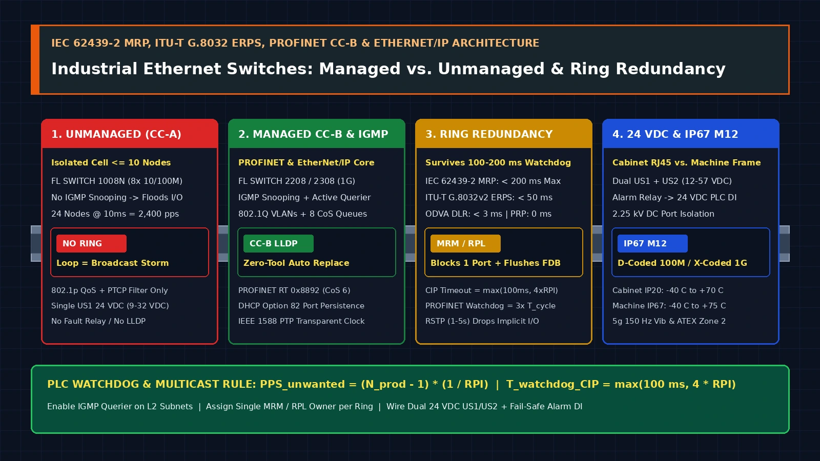
Select a managed DIN-rail Ethernet switch whenever a control network requires ring redundancy (IEC 62439-2 MRP < 200 ms, ITU-T G.8032 ERPS < 50 ms, or DLR < 3 ms), IGMP Snooping with an active Querier, PROFINET Conformance Class B (IEEE 802.1AB LLDP), or dual 24 V DC (US1/US2) power monitoring. Restrict unmanaged switches to isolated machine cells with <= 10 nodes across industrial application hardware workflows, embedded control and field communication architectures, and related technical guides.
| Specification / Capability | Unmanaged DIN-Rail (FL SWITCH 1008N) |
Managed DIN-Rail 10/100 (FL SWITCH 2208) |
Managed DIN-Rail Gigabit (FL SWITCH 2308) |
IP67 Machine-Mount M12 (FL SWITCH 1605 / 1708) |
|---|---|---|---|---|
| Port Speed & Connector | 8 × RJ45 10/100 Mbps (IP30, 22.5 mm width) |
8 × RJ45 10/100 Mbps (IP20, 45 mm width) |
8 × RJ45 10/100/1000 Mbps (IP20, 9,600 B Jumbo Frames) |
5 × M12 D-coded 4-pin (100M) or 8 × M12 X-coded 8-pin (1G, IP65/IP66/IP67) |
| Store-and-Forward Latency & Buffers | Typ. 5–10 µs (768 Kbit buffer, 2k MAC table) |
>= 6.5 µs (8k MAC table, CRC-Surveillance) |
>= 1.9 µs (8k MAC table, 9,600 B MTU) |
Store-and-Forward (4k MAC table, 40 s aging time) |
| PROFINET Class & Diagnostics | Conformance Class A (IEEE 802.1p QoS + PTCP filter only) |
Conformance Class B (LLDP 802.1AB, SNMPv1/v2/v3, DCP, PROFINET S2, Fast Startup < 500 ms) |
Conformance Class B (LLDP, SNMPv1/v2/v3, DCP, RMON, N:1 Port Mirroring) |
Conformance Class A (1605/1708 unmanaged) or CC-B on managed M12 variants |
| Ring Redundancy Support | None (looping ports causes instant broadcast storm) | IEC 62439-2 MRP (MRM & MRC < 200 ms), RSTP (1–5 s), FRD, LACP |
IEC 62439-2 MRP (MRM & MRC < 200 ms), RSTP, LACP (IEEE 802.3ad) |
None on unmanaged 1605/1708 (linear daisy-chain or star stub only) |
| Multicast & Traffic Control | None (floods EtherNet/IP multicast I/O to all ports) |
IGMP Snooping + IGMP Querier v1/v2 (RFC 4541), 32 VLANs (802.1Q), 8 QoS queues |
IGMP Snooping + IGMP Querier v1/v2 (RFC 4541), 32 VLANs, 8 QoS queues |
None on unmanaged (4 hardware IEEE 802.1p priority queues only) |
| 24 V DC Power & Fault Relay | Single US1 24 V DC (9–32 V DC, 28 mA typ, 1.56 W max), no alarm contact |
Dual redundant US1/US2 24 V DC (12–57 V DC, 185 mA typ, 4.95 W max) + 24 V DC / 100 mA alarm contact |
Dual redundant US1/US2 24 V DC (12–57 V DC, 280 mA typ, 7.8 W max) + 24 V DC / 100 mA alarm contact |
5-pin M12 power plug: single 9–32 V DC (1605, 0.96 W) or dual US1/US2 9–57 V DC (1708, 142 mA) |
| Ambient Temp & Approvals | -10 °C to +60 °C; 5g 150 Hz vib / 30g shock |
-40 °C to +70 °C; 5g vib / 30g shock; ATEX Zone 2 / UL Class I Div 2 / ISA G3 |
-40 °C to +70 °C; MTTF 381.77 yr @ 25 °C (SN 29500); ATEX / Class I Div 2 |
-40 °C to +75 °C; 5g 150 Hz vib / 30g shock; V2A 1.4301 stainless or die-cast zinc |
When an Unmanaged Industrial Ethernet Switch Is Enough—and Where It Fails
Evaluating a managed vs unmanaged industrial ethernet switch begins with the traffic profile and topology of the control cell rather than the physical port count. An industrial unmanaged switch is not an enterprise office hub: purpose-built DIN-rail units such as the Phoenix Contact FL SWITCH 1008N (Item 1085256) incorporate a 2,048-entry MAC address table, a 768 Kbit packet buffer, hardware IEEE 802.1p Quality of Service (QoS) priority queues for PROFINET and EtherNet/IP, and a PROFINET PTCP (Precision Transparent Clock Protocol) filter inside a 22.5 mm polycarbonate housing (Phoenix Contact FL SWITCH 1008N Datasheet).
However, an unmanaged din rail ethernet switch has no microprocessor management plane, no IP address, no IGMP Snooping table, no Spanning Tree or ring state machine, and no SNMP or LLDP topology reporting (ODVA PUB00035R0, FL SWITCH 1008N Datasheet). Under ODVA EtherNet/IP Media Planning and Installation Manual PUB00035R0 (Section 6.2.3), unmanaged switches must be restricted to isolated star or short daisy-chain cells that meet four strict boundary conditions:
- Maximum Node Count (
<= 10Devices): The isolated subnetwork contains10or fewer Ethernet endpoints (for example, one compact PLC, one local HMI, and six to eight unicast field devices) with no uplift trunk into the plant-wide backbone. - Low Cyclic Connection Count & Slow Update Intervals (
RPI > 10 ms): The cell carries either explicit request/response polling (Modbus TCPorCIP Class 3) or a small number of unicast cyclic I/O connections with Requested Packet Intervals (RPI) greater than10 ms(> 70 msfor non-critical monitoring) (ODVA PUB00035R0). - Strictly Loop-Free Star or Line Topology: Because Ethernet Layer 2 frames contain no Time-to-Live (
TTL) counter, connecting a redundant cable between two unmanaged switches creates an instant broadcast storm that saturates100 Mbpsports within milliseconds and halts all PLC communication. - Non-Critical Power Boundary: A single
US1power terminal (9–32 V DCon theFL SWITCH 1008N) without a fault relay is acceptable only when the switch shares the exact same24 V DCbreaker branch as the local machine actuators—meaning a power supply trip already stops the cell (FL SWITCH 1008N Datasheet).
Whenever an automation architecture requires deterministic ring failover (< 50 ms to < 200 ms), multi-axis AC drive multicast control, automated broken-device replacement (PROFINET CC-B or DHCP Option 82), VLAN isolation between OT machine traffic and IT supervisory networks, or dual 24 V DC power redundancy, a managed switch (FL SWITCH 2208 or FL SWITCH 2308) is mandatory (Rockwell ENET-RM002D-EN-P, Phoenix Contact FL SWITCH 2208 Datasheet).
Takeaway: Restrict unmanaged switches to isolated star cells with <= 10 devices and no ring connections; specify a managed switch whenever multicast cyclic I/O, ring redundancy, or port-level diagnostics are required.
Multicast Flooding, QoS Prioritization, and Protocol Conformance (EtherNet/IP, PROFINET, Modbus TCP)
Engineers migrating legacy serial fieldbuses to switched Ethernet frequently underestimate how differently cyclic industrial protocols load a Layer 2 switch fabric (for physical transceiver and gateway layer boundaries, see the RS-485, CAN, and Industrial Ethernet interface comparison).
1. Modbus RTU vs. Modbus TCP vs. Cyclic Real-Time I/O (EtherNet/IP & PROFINET RT)
In a modbus rtu vs modbus tcp comparison, serial Modbus RTU over RS-485 uses deterministic master-slave polling on a half-duplex differential pair at 9.6 kbps to 115.2 kbps: only one node transmits at any instant, so buffer congestion and packet collisions cannot occur. When migrated to Modbus TCP (TCP Port 502) or EtherNet/IP explicit messaging (CIP Class 3 over TCP/IP), communication remains low-rate unicast request/response with a generous 30-second connection timeout (Rockwell ENET-RM002D-EN-P, p. 76).
By contrast, real-time cyclic I/O protocols bypass TCP congestion control entirely to achieve deterministic millisecond or microsecond updates:
EtherNet/IPCIP Class 0 / Class 1 Implicit I/O: Transmits cyclic I/O data overUDP Port 2222at configuredRPIintervals from2 msto500 ms(Rockwell ENET-RM002D-EN-P,p. 19). Producer-to-consumer status data (such as remote I/O inputs or AC drive speed feedback shared by a controller and an HMI) frequently uses IPv4 Layer 2/3 multicast (239.192.x.x).PROFINET Real-Time (RT): Bypasses theTCP/IPandUDP/IPstacks altogether—which add variable millisecond-range stack latency—and transmits cyclic data directly inside Layer 2 Ethernet frames identified byEtherType 0x8892and prioritized viaIEEE 802.1QVLAN tag Priority6(CoS = 6) at update cycles from250 µsto512 ms(PI PROFINET System Description,Section 3.1).
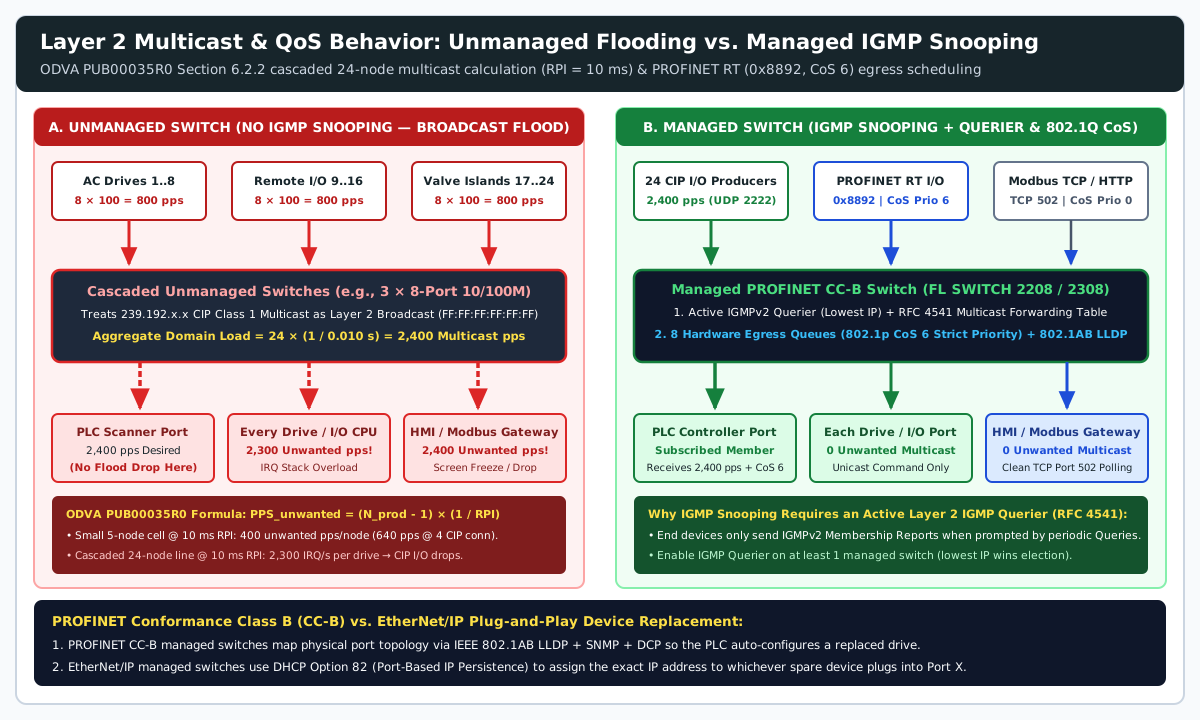
2. Worked Calculation: The Cascaded Unmanaged Switch Multicast Trap (ODVA PUB00035R0)
An unmanaged switch has no IGMP Snooping logic (RFC 4541) and therefore treats every IPv4 multicast frame (MAC 01:00:5E:xx:xx:xx) identically to a Layer 2 broadcast (FF:FF:FF:FF:FF:FF), flooding it out every port except the ingress port (ODVA PUB00035R0, RFC 4541).
Per ODVA Media Planning and Installation Manual PUB00035R0 (Sections 6.2.1–6.2.2), for Nprod multicast producer I/O devices operating at a Requested Packet Interval RPI (in seconds), the aggregate multicast packet rate and the unwanted multicast interrupt rate forced onto every other I/O device are governed by:
PPS_node        = 1 / RPI
PPS_domain      = N_prod × (1 / RPI)
PPS_unwanted_IO = (N_prod - 1) × (1 / RPI)
Walk through the three verified ODVA engineering benchmarks (ODVA PUB00035R0, pp. 61–64):
- Benchmark A — 5-Node Cell (
Nprod=5I/O blocks,1CIP connection each atRPI = 10 ms = 0.010 s):- Each I/O node transmits
1 / 0.010 s = 100multicast packets/sec (pps) and receives100unicast commandppsfrom the PLC. - On an unmanaged switch, each of the
5I/O nodes is flooded with(5 - 1) × 100=400unwanted multicastpps, while an operator workstation or HMI connected to the switch receives5 × 100=500unwanted multicastpps(ODVA PUB00035R0,Section 6.2.1).
- Each I/O node transmits
- Benchmark B — 5-Node Multi-Connection Cell (
1connection @10 ms RPI+3connections @50 ms RPIper node):- Each I/O node generates
100 + (3 × 20)=160multicastpps. - Every other I/O device receives
4 × 160=640unwanted multicastpps, and the HMI receives5 × 160=800unwantedpps(ODVA PUB00035R0,Section 6.2.1).
- Each I/O node generates
- Benchmark C — The Cascaded Unmanaged Switch Trap (
Nprod=24AC drives/I/O nodes atRPI = 10 msacross three cascaded 8-port unmanaged switches):- Cascading three 8-port unmanaged switches (
Figure 6-2inODVA PUB00035R0) does not partition the Layer 2 broadcast or multicast domain. - Total multicast traffic across the three switches reaches
24 × 100=2,400multicastpps. - Every single
100 Mbpsfield device CPU must service(24 - 1) × 100=2,300hardware receive interrupts per second solely to inspect and discard unwanted drive multicast packets (2,400unwantedppsat the HMI) (ODVA PUB00035R0,Section 6.2.2). Small embedded microcontrollers inside field I/O blocks run out of interrupt processing headroom, dropping legitimate unicast PLC output packets and faulting the line.
- Cascading three 8-port unmanaged switches (
3. Why IGMP Snooping Fails Without an Active Layer 2 IGMP Querier (RFC 4541)
Replacing unmanaged switches with a managed profinet ethernet ip switch solves multicast flooding only when both IGMP Snooping and an IGMP Querier are active (Rockwell ENET-RM002D-EN-P, p. 39; IETF RFC 4541, Section 2.1.1).
Under RFC 4541, an IGMP snooping switch listens to Layer 3 IGMPv1/v2 Membership Reports sent by end devices (such as a PLC subscribing to an I/O module’s multicast address) and builds a hardware forwarding table so multicast streams exit only on subscribed ports (RFC 4541). However, IGMP was originally designed assuming a Layer 3 multicast router sits on the subnet to transmit periodic IGMP Membership Queries. In isolated Layer 2 machine subnets with no router:
- If
IGMP Snoopingis enabled on the switches without an activeIGMP Querier, end devices send a singleIGMP Joinat boot and then fall silent because no periodicIGMP Queryarrives. - Once the switch’s multicast group aging timer expires (
typically 125–260 s), the switch purges its multicast forwarding table and either drops all cyclic I/O multicast packets or reverts to flooding (Rockwell ENET-RM002D-EN-P,p. 39). - Configuration Rule: Enable the built-in IGMP Querier function on at least one (preferably two for redundancy) managed Layer 2 switches in the VLAN (
FL SWITCH 2208/2308supportIGMP Snooping/Querier v1/v2per Phoenix Contact FL SWITCH 2208 Datasheet). UnderIGMPv2, if multiple switches have Querier enabled, the switch with the lowest IPv4 address automatically wins election as the active Querier (Rockwell ENET-RM002D-EN-P,p. 39).
4. PROFINET Conformance Class B (CC-B) vs. EtherNet/IP DHCP Option 82 Device Replacement
When an AC drive or remote I/O block fails at 2:00 AM, maintenance technicians need to bolt in a spare unit and restore production without connecting an engineering laptop to set IP addresses or device names. Managed switches provide two protocol-specific mechanisms for zero-tool replacement:
PROFINET Conformance Class B (CC-B)(IEEE 802.1AB LLDP+DCP+SNMP): As defined in PI PROFINET System Description (Sections 4.1–4.4), whileCC-Aswitches only pass prioritized frames,CC-Bmanaged switches (FL SWITCH 2208and2308) implement port-granularIEEE 802.1AB Link Layer Discovery Protocol (LLDP),SNMP(MIB-II,LLDP-EXT MIB,PDEV), andDCP(Discovery and Configuration Protocol). Every switch port continuously exchanges physical port neighborhood IDs (PLC-xyz:p001 <-> SWITCH-xyz:p007) with connected neighbors. When a factory-blank replacement device is plugged into Port 7, the PROFINET IO Controller reads the switch’sLLDPtable, verifies that the new MAC address is physically on Port 7, and automatically writes the storedAliasName, IP address, and I/O parameters to the spare device (PI PROFINET System Description,p. 17). (CC-Cadds hardware clock synchronization and bandwidth reservation forPROFINET IRTmotion control.)EtherNet/IPPer-PortDHCP Persistence(DHCP Option 82): On managed switches supportingDHCP Option 82Relay Agent Information (FL SWITCH 2208/2308per FL SWITCH 2208 Datasheet; Rockwell ENET-RM002D-EN-P,pp. 11 & 37), the switch tags everyDHCP Discoverrequest with its physical switch identifier and port number (Circuit ID), allowing the switch or DHCP server to assign the exact same IPv4 address (e.g., 192.168.1.27) to whatever replacement device is plugged into Port 4.
Takeaway: Enable IGMP Snooping together with an active IGMP Querier whenever EtherNet/IP multicast I/O exceeds 10 nodes, and specify PROFINET Conformance Class B (LLDP) or DHCP Option 82 managed switches to support tool-less field device replacement.
Deterministic Ring Redundancy: IEC 62439-2 MRP, ITU-T G.8032 ERPS, DLR, and RSTP
In linear daisy-chain topologies (using embedded 2-port switches inside drives or cascaded unmanaged switches), a single severed cable or failed middle node isolates every downstream device. Closing the line into a physical ring provides a backup path, but only if the industrial ethernet switch reconverges faster than the PLC’s real-time I/O watchdog timer.
1. Worked Calculation: PLC Real-Time Watchdog Timeout vs. Ring Failover Time
To prevent actuators from operating with stale commands during a network break, both EtherNet/IP and PROFINET enforce strict hardware connection watchdogs:
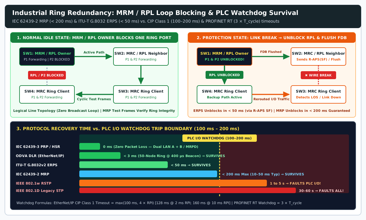
EtherNet/IPCIP Class 1 Implicit I/O Timeout Formula (Rockwell ENET-RM002D-EN-P,pp. 19 & 76):
whereT_watchdog_CIP = max(100 ms, M × RPI)Mis the connection timeout multiplier (defaultM = 4forRPI >= 25 ms, scaled automatically by the controller so the minimum timeout floor is>= 100 ms):- At
RPI = 2 ms(M = 64):Twatchdog_CIP=64 × 2 ms=128 ms - At
RPI = 10 ms(M = 16):Twatchdog_CIP=16 × 10 ms=160 ms - At
RPI = 25 ms(M = 4):Twatchdog_CIP=4 × 25 ms=100 ms - At
RPI = 50 ms(M = 4):Twatchdog_CIP=4 × 50 ms=200 ms
- At
PROFINET RTIO Watchdog Formula (PI PROFINET System Description,Section 3.1):
whereT_watchdog_PN = k × T_cyclek = 3is the standard watchdog factor (3consecutive missed cyclic frames) andTcycleis the configured bus update cycle (250 µsto512 ms). In a PROFINET ring configured forIEC 62439-2 MRP, the IO device watchdog hold time is set to>= 200 ms(for example,Tcycle=64 ms×3=192 msor16 ms×13=208 ms) so a single ring switchover never trips the PLC fault handler.
Compare that 100 ms to 200 ms real-time survival window against standard IT and OT redundancy protocols:
| Redundancy Protocol | Governing Standard | Loop Prevention & Node Roles | Worst-Case Recovery Time | Survives 100–200 ms PLC I/O Watchdog? |
Primary Industrial Ecosystem |
|---|---|---|---|---|---|
| STP (Spanning Tree) | IEEE 802.1D |
Root Bridge + Blocked Port via passive BPDU max-age/forward-delay timers |
30 to 60 seconds |
No — faults all CIP Class 1 and PROFINET RT I/O; even risks 30 s Modbus TCP drop |
Legacy enterprise IT (obsolete in industrial control) |
| RSTP (Rapid Spanning Tree) | IEEE 802.1w / 802.1D-2004 |
Root Bridge + Alternate/Backup ports with active proposal/agreement handshake | 1 to 5 seconds |
No — 1,000–5,000 ms exceeds 100–200 ms I/O watchdog; acceptable only for 30 s TCP/SCADA |
Upper plant IT/OT backbone & Modbus TCP SCADA trunks |
| MRP (Media Redundancy Protocol) | IEC 62439-2 |
1 Media Redundancy Manager (MRM) blocks 1 ring port + up to 50 Clients (MRC) |
< 200 ms guaranteed (10–50 ms typ); 0 ms with MRPD (IEC 61158) |
Yes — deterministic < 200 ms recovery matches PROFINET watchdog hold time |
PROFINET IO standard (Phoenix Contact, Siemens, Hirschmann) |
| ERPS (Ethernet Ring Protection Switching) | ITU-T G.8032 / Y.1344 (v1 / v2) |
RPL Owner + RPL Neighbor block Ring Protection Link; ETH-CC OAM + R-APS(SF) over APS VLAN |
< 50 ms |
Yes — survives both 100–200 ms CIP Class 1 (RPI >= 2 ms) and PROFINET RT watchdogs |
Multi-vendor DIN-rail rings, ladder sub-rings (G.8032v2), Cisco IE, Moxa |
| DLR (Device Level Ring) | ODVA EtherNet/IP Spec |
1 Active Ring Supervisor (blocks 1 port, 400 µs beacons) + Backup Supervisor + Ring Nodes |
< 3 ms (50-node ring) |
Yes — easily survives CIP Motion and 2 ms RPI (128 ms timeout) implicit I/O |
Rockwell Automation / ODVA embedded-switch drives & Stratix |
| PRP / HSR (Parallel / Seamless Redundancy) | IEC 62439-3 (Clauses 4 & 5) |
Dual Attached Nodes (DAN) or RedBox send duplicate frames over independent LAN A + LAN B (PRP) or dual ring (HSR) |
0 ms (bumpless, zero packet loss) |
Yes — zero switchover delay for safety I/O, IEC 61850 substations, and process DCS |
Power utilities (IEC 61850), oil & gas DCS, high-availability safety |
2. Inside IEC 62439-2 MRP: Media Redundancy Manager (MRM) vs. Clients (MRC)
Standardized in IEC 62439-2 and integrated across managed PROFINET switches such as the Phoenix Contact FL SWITCH 2208 (2702327) and FL SWITCH 2308 (2702652), iec 62439-2 mrp ring redundancy supports up to 50 switches or end devices in a physical ring with a guaranteed maximum reconfiguration time of < 200 ms (PI PROFINET System Description, Section 6.7, Figure 24; FL SWITCH 2208 Datasheet):
- Normal Idle State: Exactly one switch in the ring is configured as the Media Redundancy Manager (
MRM), while all other switches act as Media Redundancy Clients (MRC). TheMRMlogically blocks one of its two ring ports for regular data traffic—converting the physical ring into a loop-free logical line—while transmitting cyclicMRP_Testframes out one ring port and receiving them on the blocked ring port (PI PROFINET System Description,p. 25). - Protection Failover State: If a copper patch cord or fiber trunk breaks—or an
MRCloses power—an adjacentMRCdetects Loss of Signal (LOS) and transmitsMRP_LinkDownnotification frames, or theMRMdetects missingMRP_Testframes. TheMRMimmediately transitions its blocked ring port to theForwardingstate and broadcasts a topology-change frame instructing allMRCswitches to flush their MAC Filtering Databases (FDB) so traffic reroutes within< 200 ms(10–50 mstypical) (PI PROFINET System Description,Section 6.7). - Bumpless
MRPD(IEC 61158): ForPROFINET IRTisochronous motion control (CC-C), Media Redundancy for Planned Duplication (MRPD) transmits cyclic frames simultaneously in both directions around the ring so the receiver continues operating with0 msswitchover delay (PI PROFINET System Description,p. 25).
3. Inside ITU-T G.8032 ERPS (v1/v2): Sub-50 ms Multi-Vendor Ring & Sub-Ring Protection
When a ring must interconnect multi-vendor switches across both EtherNet/IP and PROFINET backbones—or scale into interconnected ladder and sub-ring topologies—engineers deploy ITU-T G.8032 / Y.1344 Ethernet Ring Protection Switching (ERPS) (ITU-T G.8032 Overview, Cisco IE3100 G.8032 Guide):
- RPL Owner & RPL Neighbor: One physical link in the ring is designated as the Ring Protection Link (
RPL). InG.8032v2, both the RPL Owner and the adjacent RPL Neighbor block their respective ends of theRPLduring the normalIdlestate (xSTPmust be disabled on all ring ports) (ITU-T G.8032 Overview, Cisco IE3100 G.8032 Guide). ETH-CCMonitoring &R-APS (SF)Signaling (< 50 ms): Ring links are monitored via hardwareIEEE 802.1ag / ITU-T Y.1731Continuity Check (ETH-CC) OAM messages. Upon a link fault, the adjacent switches block the failed port, flush theirFDBMAC tables, and multicast Ring Automatic Protection Switching — Signal Fail (R-APS (SF)) frames over a dedicatedAPS ChannelVLAN (ITU-T G.8032 Overview). Upon receivingR-APS (SF), theRPL Ownerunblocks theRPLand flushes itsFDBin< 50 ms—preserving even2 ms RPI(128 mstimeout)EtherNet/IPCIP Class 1 connections.- Guard, Hold-Off, and Wait-to-Restore (
WTR) Timers: To prevent transient contact bounce or repaired links from causing forwarding loops,G.8032enforces a Guard Timer (10 msto2 s, default500 ms) to ignore staleR-APSframes, a Hold-Off Timer (0to10 sin100 mssteps) to coordinate with underlying optical transport protection, and a Wait-to-Restore (WTR) Timer (1to12 minutes) before theRPL Ownerre-blocks theRPLand transmitsR-APS (NR, RB)(ITU-T G.8032 Overview, Cisco IE3100 G.8032 Guide).
Takeaway: Never enable STP or RSTP on real-time I/O rings where PLC watchdogs expire in 100–200 ms; configure exactly one MRM in an IEC 62439-2 MRP ring (< 200 ms) or one RPL Owner in an ITU-T G.8032 ERPS ring (< 50 ms).
IEEE 1588 PTP Time Synchronization, Gigabit Uplinks, and Port Mirroring Diagnostics
Beyond multicast pruning and ring recovery, three switch-fabric parameters separate precision control panels from intermittent packet-loss failures: hardware timestamping (IEEE 1588 PTP), store-and-forward serialization latency (100 Mbps vs. 1 Gbps), and duplex autonegotiation management.
1. IEEE 1588v2 PTP (CIP Sync / PTCP) End-to-End Transparent Clocks
Standard Network Time Protocol (NTP, RFC 1305) synchronizes controller clocks only to within milliseconds (10-3 s). Multi-axis electronic camming (CIP Motion), sequence-of-events (SOE) fault recording, and PROFINET IRT require IEEE 1588 Precision Time Protocol (PTP), which synchronizes distributed clocks to within tens of nanoseconds (10-9 s) (Rockwell ENET-RM002D-EN-P, pp. 47–50).
When IEEE 1588 Sync and Delay_Req event packets traverse an unmanaged store-and-forward switch, variable queue depth creates asymmetrical packet latency (residence time jitter) that destabilizes the slave clock’s phase-locked servo loop. A managed switch supporting IEEE 1588 End-to-End (E2E) Transparent Clock operation timestamps each PTP event frame in hardware at ingress (tin) and egress (tout), calculates the exact switch residence time (tresidence = tout - tin), and adds that delay into the PTP frame’s correctionField with 1 picosecond (10-12 s) resolution—allowing downstream servo drives to subtract switch queuing jitter completely without requiring the switch to participate in the Best Master Clock Algorithm (BMCA) (Rockwell ENET-RM002D-EN-P, pp. 48–50).
2. Store-and-Forward Switching Latency & 9,600-Byte Jumbo Frames (10/100M vs. Full Gigabit)
Comparing the Fast Ethernet Phoenix Contact FL SWITCH 2208 (2702327, 8 × 10/100 Mbps) against the Full Gigabit FL SWITCH 2308 (2702652, 8 × 10/100/1000 Mbps) highlights the serialization and buffer advantages of a Gigabit backplane (FL SWITCH 2208 Datasheet, FL SWITCH 2308 Datasheet):
- Minimum Store-and-Forward Latency: Drops from
>= 6.5 µson the10/100 MbpsFL SWITCH 2208down to>= 1.9 µson the GigabitFL SWITCH 2308—cutting per-hop switching delay by70%across multi-switch rings (FL SWITCH 2208 Datasheet, FL SWITCH 2308 Datasheet). - Maximum Transmission Unit (
MTU/ Jumbo Frames): Standard10/100 Mbpsswitches cap Ethernet frame size at1,518 bytes(1,522 byteswith802.1QVLAN tag). The GigabitFL SWITCH 2308(and theIP67FL SWITCH 1708) supports9,600-byteJumbo Frames (FL SWITCH 2308 Datasheet, FL SWITCH 1708 Datasheet). WhenGigE Visionmachine-vision inspection cameras share a machine network with PLC I/O,9,600-byteJumbo Frames reduce camera frame fragmentation by6×whileIEEE 802.1pstrict-priority queuing (CoS 6) allows64-bytePROFINET/CIP I/O packets to preempt between camera frames in< 80 µson a1 Gbpslink (compared to800 µson a100 Mbpslink).
3. The Full/Half-Duplex Autonegotiation Mismatch Failure Mode & SPAN Port Mirroring
One of the most destructive commissioning errors documented in Rockwell Automation ENET-RM002D-EN-P (pp. 28–29) is locking one end of an industrial link to 100 Mbps Full Duplex (Autonegotiation Disabled) while leaving the partner port set to Auto-Negotiate:
- Per
IEEE 802.3u, when Port A has autonegotiation disabled, it stops transmitting Fast Link Pulses (FLP). - Port B (set to
Auto-Negotiate) detects the100BASE-TXcarrier energy via parallel detection (100 Mbps), but because it receives noFLPduplex advertisement, the IEEE standard forces Port B to fall back to100 Mbps Half Duplex(Rockwell ENET-RM002D-EN-P,p. 28). - Resulting Failure Mode: Port A (
Full Duplex) transmits whenever it has data without checkingCSMA/CDcarrier sense, while Port B (Half Duplex) aborts transmissions, logs massive Late Collisions, FCS/CRC errors, and Alignment Errors (visible via RMON / CRC-Surveillance on FL SWITCH 2208/2308), and drops cyclic I/O under load (Rockwell ENET-RM002D-EN-P,p. 29; FL SWITCH 2208 Datasheet). - Commissioning Rule: Leave
IEEE 802.3Auto-Negotiation enabled on both ends (PROFINET CC-A/CC-Bmandates autonegotiation and auto-crossover per PI PROFINET System Description,Section 4.1), or manually lock both endpoints to identical speed and duplex settings when required by legacy hardware. Use the managed switch’sN:1 Port Mirroring(SPAN) feature to copy ingress/egress frames from suspect PLC ports to a diagnostic laptop running Wireshark without inserting a physical tap that breaks the link (Rockwell ENET-RM002D-EN-P,p. 61; FL SWITCH 2208 Datasheet).
Takeaway: Specify IEEE 1588 E2E Transparent Clock switches for motion control, use Full Gigabit (>= 1.9 µs latency, 9,600 B Jumbo Frames) when sharing links with vision cameras, and never mix Auto-Negotiate with forced Full Duplex on the same link.
DIN-Rail Hardware Integration: Dual 24VDC Redundant Power, Fault Relays, and IP67 M12 Cabling
A deterministic ring protocol cannot keep a production line running if a single tripped 24 V DC breaker powers down the switch or if cabinet-grade RJ45 plugs vibrate loose on a moving machine frame.
1. Wiring a Dual 24VDC Redundant Power Input Switch (US1 / US2) & Surge Coordination
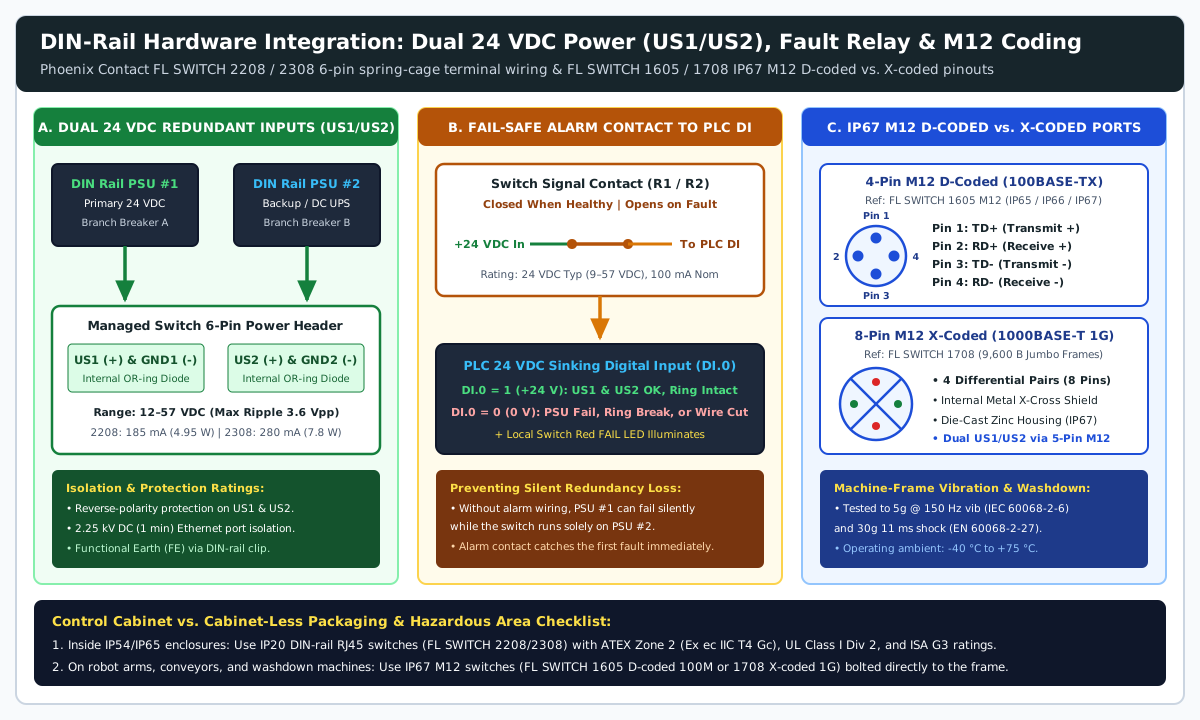
Entry-level unmanaged switches (FL SWITCH 1008N) provide only a single US1 supply terminal (9–32 V DC, 28 mA typical at 24 V DC, 1.557 W max dissipation) (FL SWITCH 1008N Datasheet). By contrast, industrial managed switches (FL SWITCH 2208 and 2308) and heavy-duty machine switches (FL SWITCH 1708) operate as a dual 24vdc redundant power input switch using internally diode/MOSFET-decoupled supply rails US1 and US2 on a removable 6-position spring-cage terminal block (FL SWITCH 2208 Datasheet, FL SWITCH 2308 Datasheet):
- Wide DC Input Window & Ripple Tolerance: Rated
24 V DCnominal across a continuous12 V DC to 57 V DCoperating range (9–57 V DConFL SWITCH 1708), with maximum permissible ripple of3.6 VPP, reverse-polarity protection,2.25 kV DC(1 min) Ethernet port dielectric isolation, and500 V DC(1 min) supply-to-Functional-Earth (FE) isolation (FL SWITCH 2208 Datasheet). - Power Budgeting: The
8-port10/100MFL SWITCH 2208draws185 mAtypical at24 V DC(4.95 Wmax thermal dissipation), while the8-port GigabitFL SWITCH 2308draws280 mAtypical at24 V DC(7.8 Wmax dissipation,MTTF = 381.77 yearsat25 °CperSN 29500) (FL SWITCH 2208 Datasheet, FL SWITCH 2308 Datasheet). - Independent Supply & SPD Architecture: Wire
US1 (+)andGND1 (-)to Primary24 V DCdin rail power supply#1 and wireUS2 (+)andGND2 (-)to Secondary24 V DCdin rail power supply#2 (or a24 V DCUPS module). When documenting AC feeder versus DC secondary load budgets, follow the 24 V DC power supply sizing and boundary checklist. To protectUS1/US2and inter-cabinet copper ports from switching transients on external24 V DCruns, install a Type 324 V DCDIN-rail surge arrester (Uc=34 V DC,Up<=200 V) and transition outdoor inter-building Ethernet trunks to optical fiber as detailed in the DIN-rail Type 1, Type 2, and Type 3 surge protection coordination guide and power and protection engineering records.
2. Fail-Safe Alarm Relay / Signal Contact Wiring to a 24 V DC PLC Digital Input
Wiring US1 and US2 to two separate power supplies creates a hidden maintenance trap if the switch’s fault contact is left unconnected: when Primary PSU #1 fails, the internal OR-ing circuit seamlessly shifts the load to Secondary PSU #2 with zero network interruption. Months later, when Secondary PSU #2 trips or undergoes maintenance, the switch loses power completely.
On the FL SWITCH 2208 and 2308, the 6-pin power connector integrates a potential-free Alarm Signal Contact (R1 / R2, rated 24 V DC typical, 9–57 V DC range, 100 mA nominal / 0.7 A max for 1 min) paired with a top-mounted red FAIL LED (FL SWITCH 2208 Datasheet, FL SWITCH 2308 Datasheet):
- Normal State (Closed): When both
US1andUS2are above the undervoltage threshold and all monitored ring/device ports maintain link, the internal alarm contact stays closed, passing+24 V DC(Logic 1) to the connected PLC sinking digital input (DI.0). - Fault State (Open — Wire-Break Safe): If either
US1orUS2drops out, a monitored ring port loses link, or the diagnostic wire itself breaks, the contact opens (DI.0 = 0 V / Logic 0), logging an immediate HMI maintenance alarm while the machine continues running on the healthy supply rail.
3. Control-Cabinet IP20 RJ45 vs. Machine-Mount IP67 M12 D-Coded and X-Coded Switches
Inside a sealed IP54 or IP65 control cabinet, DIN-rail IP20 switches (FL SWITCH 2208 / 2308) use shielded RJ45 patch cords and carry hazardous-location approvals including ATEX / IECEx Zone 2 (Ex ec IIC T4 Gc), UL Class I Division 2 Groups A, B, C, D (T4), ISA S71.04-2013 Class G3 Harsh corrosive-gas immunity, and marine (DNV GL, ABS, LR) certifications across -40 °C to +70 °C (FL SWITCH 2208 Datasheet).
However, when switches are bolted directly onto robot arms, conveyors, or washdown packaging machinery outside an enclosure (see the packaging machine sensor and actuator interface checklist), standard RJ45 plastic latches fatigue under continuous 5g (150 Hz) vibration (IEC 60068-2-6) and 30g (11 ms) mechanical shock (EN 60068-2-27), and fail high-pressure water washdown (ODVA PUB00035R0, Section 7.1.2; FL SWITCH 1605 M12 Datasheet). For cabinet-less machine mounting across -40 °C to +75 °C, specify IP65 / IP66 / IP67 circular M12 switches:
4-Pin M12 D-Coded(100BASE-TXFast Ethernet — e.g.,Phoenix Contact FL SWITCH 1605 M12,2700200): Uses a30 mmnarrowPBThousing with aV2Astainless-steel (1.4301) mounting plate, a5-pin M12power plug (Pin 1 = Us 24 V DC,Pin 3 = GND,Pin 5 = Functional Earth FE;40 mAtyp /0.96 W), and5female4-pin M12 D-codedEthernet ports mechanically keyed perODVA PUB00035R0Section 7.1.2so they cannot mis-mate with A-coded sensor plugs (ODVA PUB00035R0, FL SWITCH 1605 M12 Datasheet):- Pin 1:
TD+(Transmit Data +) - Pin 2:
RD+(Receive Data +) - Pin 3:
TD-(Transmit Data -) - Pin 4:
RD-(Receive Data -)
- Pin 1:
8-Pin M12 X-Coded(1000BASE-TFull Gigabit — e.g.,Phoenix Contact FL SWITCH 1708,1196228): Houses8female8-pin M12 X-codedGigabit ports (9,600-byteJumbo Frame support) plus dual redundantUS1/US2(9–57 V DC,142 mAtyp) power inside a1,110 gdie-cast zinc enclosure ratedIP65,IP66, andIP67(1 mwater immersion for30 min) (FL SWITCH 1708 Datasheet). An internal X-shaped metal pair shield isolates all four bidirectional differential pairs (BI_DA±,BI_DB±,BI_DC±,BI_DD±) to eliminate near-end crosstalk (NEXT) up to500 MHz.
Takeaway: Wire US1 and US2 to independent 24 V DC din rail power supply rails, connect the switch’s 24 V DC / 100 mA alarm contact to a PLC digital input, and replace IP20 RJ45 switches with IP67 M12 D-coded (100M) or X-coded (1G) switches on exposed machine frames.
Control Panel Switch Specification & Commissioning Checklist
Verify these seven engineering criteria during schematic design and factory acceptance testing (FAT) before releasing an industrial Ethernet control panel:
| Check Item | Engineering Requirement & Standard Clause | Target Value / Verification Criterion |
|---|---|---|
| 1. Multicast Load & Switch Class | Calculate aggregate EtherNet/IP multicast load PPS = N_prod × (1 / RPI) (ODVA PUB00035R0, Section 6.2.2–6.2.3) |
Unmanaged switch allowed only if <= 10 nodes, RPI > 10 ms, and no ring; otherwise use managed switch |
| 2. IGMP Snooping + Active Querier | IETF RFC 4541 & Rockwell ENET-RM002D-EN-P (p. 39) multicast table maintenance on Layer 2 subnets |
Enable IGMP Snooping on all switches and enable IGMPv2 Querier on >= 1 managed switch (lowest IP wins) |
| 3. PROFINET CC-B / DHCP Option 82 | Automated zero-tool device replacement (PI PROFINET Spec Section 4.2 / Rockwell ENET-RM002D p. 37) |
Verify IEEE 802.1AB LLDP + SNMP + DCP enabled (CC-B) for PROFINET, or per-port DHCP Option 82 for EtherNet/IP |
| 4. Ring Manager & PLC Watchdog Margin | Compare ring failover against T_watchdog_CIP = max(100 ms, 4 × RPI) and T_watchdog_PN = 3 × T_cycle |
Assign exactly 1 MRM (IEC 62439-2 MRP < 200 ms) or RPL Owner (G.8032 ERPS < 50 ms); never use STP/RSTP for I/O rings |
| 5. Speed / Duplex Autonegotiation | Prevent Full/Half-Duplex mismatch late collisions (IEEE 802.3u / Rockwell ENET-RM002D pp. 28–29) |
Keep Auto-Negotiate enabled on both link partners (PROFINET mandatory), or lock both ends identically; check RMON CRC = 0 |
6. Dual 24 V DC (US1/US2) & Alarm DI |
Redundant 12–57 V DC supply separation & fail-safe fault contact (FL SWITCH 2208 Datasheet) |
Wire US1 to PSU #1 and US2 to PSU #2; wire R1/R2 alarm contact (24 V DC / 100 mA) to PLC DI (Logic 1 = OK, 0 = Fault) |
| 7. Cabinet IP20 vs. Machine IP67 M12 | Match connector ingress & vibration (5g 150 Hz IEC 60068-2-6) to mounting zone (FL SWITCH 1605, 1708) |
IP20 RJ45 (ATEX Zone 2 / Class I Div 2) inside enclosures; IP67 M12 D-coded (100M) or X-coded (1G, 9,600 B MTU) on machine frames |
Takeaway: Verify all seven commissioning checkpoints—multicast budget, active IGMP Querier, LLDP/Option 82 port persistence, single ring manager, duplex autonegotiation, dual 24 V DC alarm loop, and connector rating—before placing an industrial Ethernet network into production.