A zero-cross solid-state relay on a half-wave solenoid can fail to turn on, and a random-turn-on solid-state relay on a cold metal heater can be asked to pass an inrush the output die is not rated to repeat. The turn-on circuit follows the load waveform. Surge current and heat-sink thermal resistance then decide whether that choice survives.
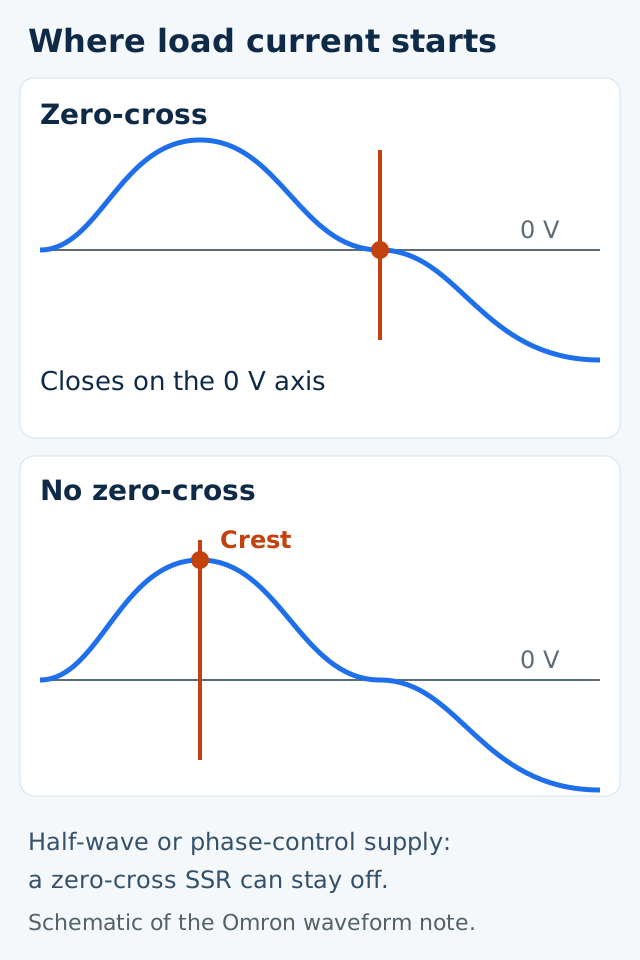
A solid-state relay for an AC load is chosen first by the zero-crossing circuit. In Omron technical guide CSM_SSR_TG_E_4_1, the zero-cross function turns the SSR on when the AC load voltage is at 0 V or close to 0 V. Random turn-on, in this page, means the behavior the same guide draws for an SSR without that function: load current can start at the phase present when the input turns on, and the sudden current change produces noise on the supply and in the air. The guide does not print an I²t figure for these models. It prints withstand surge current in amperes, and it prints heat as voltage drop times current. Use those published conditions for the named series. A different maker’s firing window and surge curve are separate documents.
| Input or item | Published value or condition | Why it matters |
|---|---|---|
| Zero-cross turn-on | AC load voltage at 0 V or close to 0 V | Sets where load current starts |
| Lamp inrush | About 10 to 15 times rated current | Peak must not exceed half the surge rating |
| Motor inrush | 5 to 10 times rated, for a longer time | Peak must be less than half the surge rating, plus overvoltage protection at turn-off |
| Transformer inrush | 10 to 20 times rated for 10 to 500 ms | Open secondary gives the maximum; repetitive use needs twice Ipeak |
| Heat, triac example | G3NA-210B, 1.6 V times 8 A = 12.8 W | Sets the watts the sink must remove |
| Heat sink | Y92B-N100 is 1.63 °C/W for G3NA-220B | A higher thermal resistance is not an equivalent sink |
Where the output is allowed to start
The zero-cross function reduces clicking when a load turns on, and it suppresses inrush on loads such as lamps, heaters, and motors so the inrush-protection circuit can be smaller. A resistive heater switched from a voltage-output temperature controller is the guide’s ordinary ON/OFF case, and a zero-cross SSR suppresses most of the noise. All-metal and ceramic heaters are outside that case: their resistance at normal temperature is low, so the SSR sees an overcurrent. For those heaters the guide points to a power controller such as the G3PX with a long soft-start, or a constant-current SSR.
An SSR without the zero-cross function is the guide’s answer when the load supply itself is half-wave rectified or is a phase-control supply. AC electromagnetic counters and solenoids with a built-in diode never present a full sine wave at the SSR output, so a zero-cross circuit can fail to turn on. Two workarounds are printed, and both stop at a half-wave rectified brake coil, which needs an SSR designed for DC loads. The guide also says application is not possible for a 200 VAC half-wave rectified circuit, and it prints the peak as 283 V.
Cycle control is a third behavior, not a synonym for random turn-on. With the G32A-EA, output is turned on and off at a fixed 0.2 s interval from a 4 to 20 mA controller. Optimum cycle control still uses the zero-cross principle and decides ON or OFF each half-cycle. Because inrush then flows five times a second, the guide warns that a transformer primary is a poor place for cycle control: the SSR can be destroyed if the rating has too little margin, and the load breaker can trip.
Dominant failure mode and the prevention the guide prints
| Load or circuit | Dominant failure mode | Prevention in CSM_SSR_TG_E_4_1 |
|---|---|---|
| Half-wave counter or solenoid with a zero-cross SSR | SSR does not turn on | SSR without zero-cross, or a bleeder of about 20% of SSR load current. Brake coil: DC-load SSR |
| Incandescent or halogen lamp | Inrush about 10 to 15 times rated damages the output if it exceeds half the surge rating | Keep the peak at or below half the withstand surge current. Above that, repetitive inrush can damage the output element |
| Motor | Inrush 5 to 10 times rated, then counter-EMF at turn-off | Peak below half the surge rating, and overvoltage protection |
| Transformer, secondary open | Energizing current 10 to 20 times rated for 10 to 500 ms | Energizing current at or below half the surge rating. Repetitive switching: surge rating at least twice Ipeak |
| All-metal or ceramic heater | Low cold resistance overcurrents the SSR | Long soft-start power controller, or a constant-current SSR |
| Inverter waveform on the load supply | Large dV/dt can misfire the SSR and keep it from resetting | Do not use an inverter-controlled supply as the load supply |
| Self-holding logic built from SSRs | The SSR does not provide the mechanical latch | Self-holding circuits use mechanical relays |
| Full-wave rectified load | Rectangular current, so the triac can fail to reset | A -V model or a power MOSFET relay. The guide names G3F-203SL-V, G3H-203SL-V, G3DZ, G3RZ, and G3FM |
| Output element short | The load stays on after the input is removed | A contactor or circuit breaker on the load supply. The indicator only shows input current |
If the load is half-wave rectified or phase-controlled and the SSR has a zero-cross function, select an SSR without that function. The troubleshooting chart states that fix directly. The bleeder alternative is about 20% of the SSR load current, and it does not extend to a half-wave brake coil.
If lamp or transformer peak inrush exceeds half the withstand surge current, or motor or capacitor peak inrush is not below half that rating, the selection rule in this guide is missed. Lamp and transformer peaks must not exceed half the surge rating. Motor inrush and capacitor charge current must be less than half. An OFF SSR across a capacitor also needs a voltage rating of twice the supply, because the supply plus the capacitor voltage appears across the output.
If a substitute heat sink is above 1.63 °C/W, it is not the equivalent Omron allows for the G3NA-220B. The Y92B-N100 is 1.63 °C/W. The guide’s own example of an acceptable substitute is 1.5 °C/W, which is lower. Thermal resistance is the temperature rise per watt. A smaller number radiates more heat.
Worked surge and heating examples
Heating for a triac, thyristor, or power-transistor output is the output-on voltage drop times the carry current. For a G3NA-210B carrying 8 A, the guide calculates P = 1.6 V × 8 A = 12.8 W.
A power-MOSFET output uses on-state resistance instead. For a G3RZ at 0.5 A and 2.4 Ω, P = 0.5² × 2.4 Ω = 0.6 W. On-state resistance rises with junction temperature. When load current is high, the guide’s shortcut multiplies that 2.4 Ω by 1.5 and shows P = 3.6 W, which is 1² × 2.4 × 1.5.
The panel example uses the same 1.6 V drop. Twenty G3PA-240B units in continuous operation at 30 A produce 1.6 V × 30 A × 20 = 960 W. Other devices add 500 W, so P1 = 1,460 W. The panel is 2.5 × 2 × 0.5 m, bottom excluded, desired interior 40 °C, ambient 30 °C, and overall heat-transfer coefficient k = 5 W/m²°C, inside the guide’s practical 4 to 6 range for a panel with no fan. Surface heat flow is Q = 5 × (40 − 30) × (2.5 × 2 × 2 + 0.5 × 2 × 2 + 2.5 × 0.5) = 662.5 W. Required extra cooling is P2 = 1,460 − 663 = 797 W. The surface is not enough. The guide then points to a ventilation fan, and to a panel air conditioner when the fan is not enough.
Transformer inrush is estimated from primary DC resistance when the secondary is open. Ipeak = Vpeak / R = (1.414 × V) / R. At 220 V and 3 Ω, Ipeak = (1.414 × 220) / 3 = 103.7 A. Actual inrush is lower once self-reactance is present. The surge rating is specified for non-repetitive operation, about one or two operations a day. Repetitive switching needs a withstand surge current twice that peak, 207.4 A in this example. The G3NA-220B is printed at 220 A withstand in the forward/reverse protection example, which is a different circuit: the guide’s protective resistor line there is R > 220 V × √2 / 200 A = 1.4 Ω, and resistor power is P = I²R times a safety factor of 3 to 5. Forward and reverse also need at least 30 ms between the two SSR inputs, because a triac stays on until load current reaches zero.
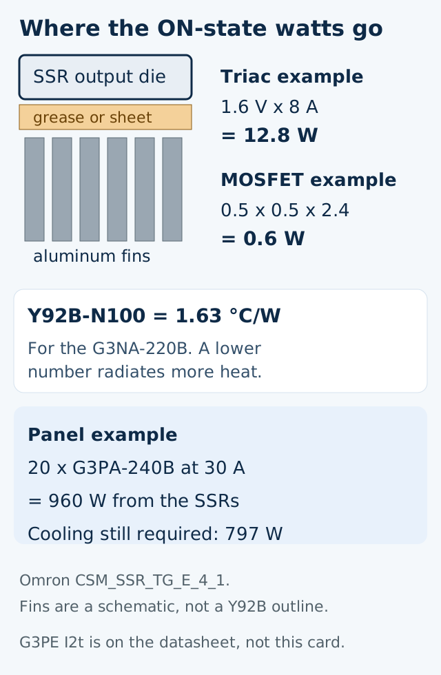
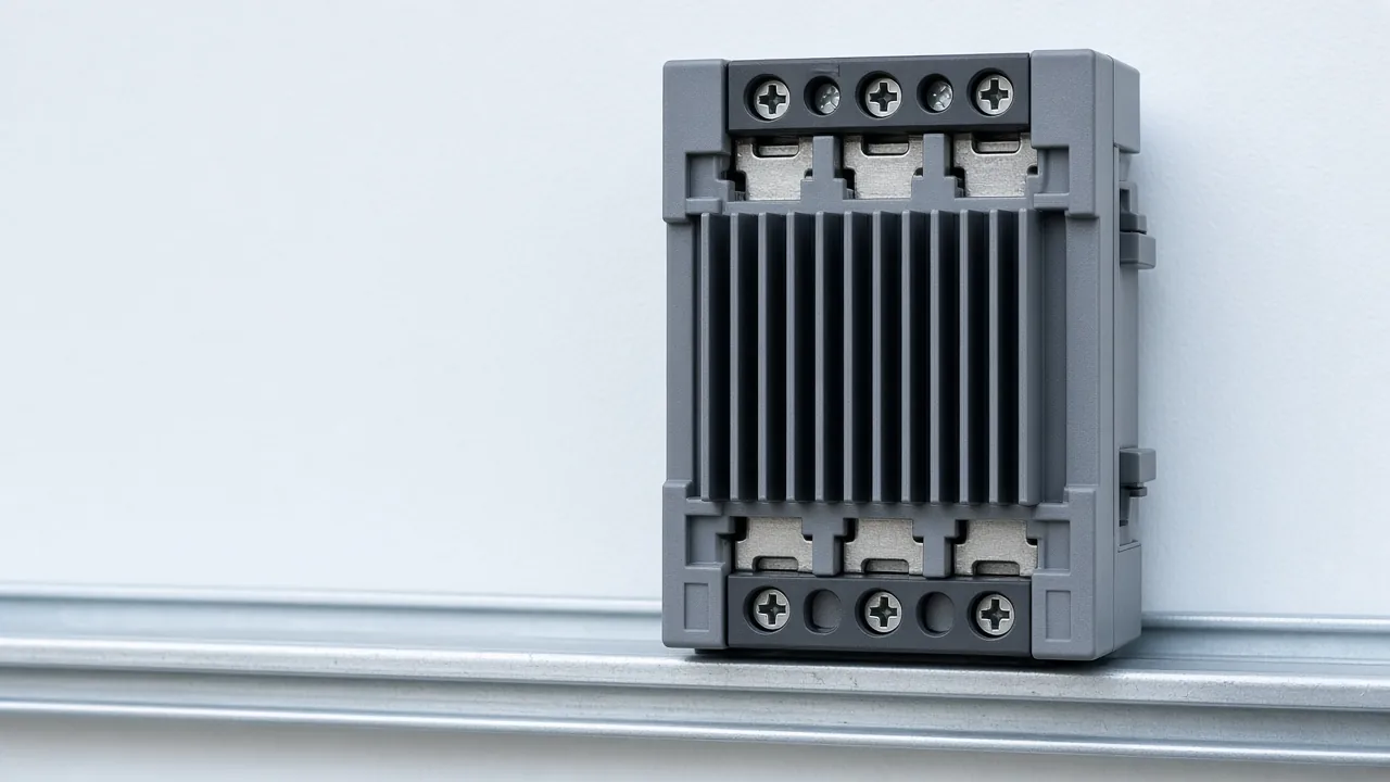
G3NA, G3NE, and three-phase G3PB models in the guide have no integral sink. Pairings printed as ideal are G3NA-220B with Y92B-N100, G3NE-210T(L) with Y92B-N50, and G3PB-235B-3H-VD with Y92B-P200. Steel panel stock is a poor sink above 10 A because its conductivity is 20 to 50 W·m·°C against 150 to 220 for aluminum. Silicone grease, the guide names Toshiba YG6260 or Shin-Etsu G746, fills the gap between SSR and sink. A heat-conduction sheet generally moves less heat, and the guide says to reduce load current by about 10% from the load-current versus ambient-temperature graph when a sheet is used. Painted panels and wood are excluded: paint raises thermal resistance, and wood can carbonize.
The DIN-rail form of the same choice is the G3PE heater series, datasheet CSM_G3PE_J174-E1_2_1. The relays mount to DIN track or with screws, and the applicable track is TR35-15Fe (IEC 60715). The ordering table marks zero-cross “Yes” on G3PE-@B and “No” on G3PE-@BL. For the single-phase 100 to 240 VAC B models, operate time is 1/2 of the load power-source cycle plus 1 ms maximum. The BL column is 1 ms maximum. Release time is 1/2 cycle plus 1 ms maximum on both columns, so omitting zero-cross shortens turn-on and does not shorten turn-off. At 50 Hz the half-cycle term is 1/(2 × 50) = 10 ms, so the zero-cross operate ceiling is 11 ms. That 11 ms is the printed half-cycle term plus the printed 1 ms, not a separate cell. G3PE-215B(L) is 0.1 to 15 A at 40 °C, rated load voltage 100 to 240 VAC. Its inrush-current resistance is 150 A at 60 Hz for 1 cycle, and the permissible I²t reference value beside that column is 121 A²s. Input current, specified at 25 °C ambient, is 7 mA maximum on the zero-cross models and 15 mA maximum on the BL models, both at 12 to 24 VDC rated input. The technical guide’s surge sections used above are in amperes. This I²t figure is the datasheet reference value for that G3PE column, not a conversion of the G3NA-220B’s 220 A.
The SSR input is isolated by a photocoupler. That isolation stage has its own current-transfer and common-mode limits, covered in the optocoupler CTR and high-speed logic guide. The control-side port that drives the input is a separate record; the RS-485, CAN, and Ethernet comparison keeps the electrical interface, the link, and the application meaning apart. Both pages sit on the embedded-control route.
What to copy into the project record
Copy the SSR series, whether the ordering code includes the zero-cross function, the load class, the measured or datasheet inrush peak, the surge rating and whether the duty is repetitive, the sink thermal resistance, and the grease or sheet. Part identity belongs in the ordering-code and marking record. Operating assumptions stay tied to the original file, as in the datasheet condition checklist. Panel wattage that does not match the 2.5 × 2 × 0.5 m example needs its own surface area in Q = k × (Th − Tc) × S.
Method and sources
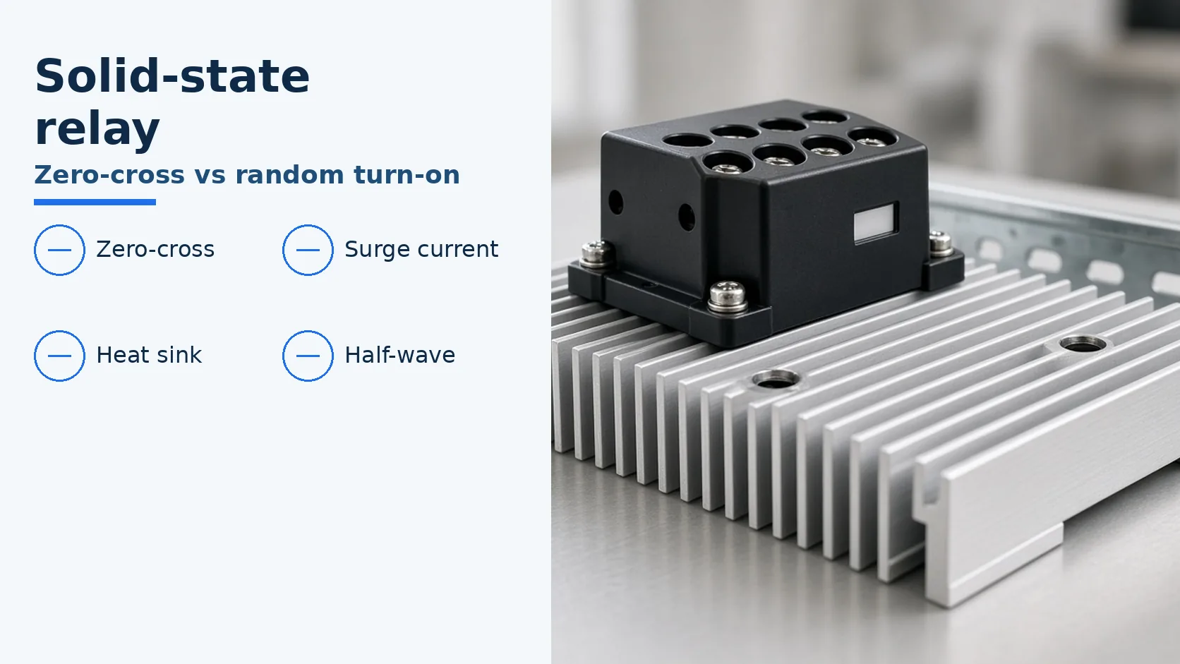
Figures and the worked arithmetic are taken from Omron Solid State Relays Technical Guide CSM_SSR_TG_E_4_1, the PDF returned on 19 October 2026 by the current Omron Europe technical-manual URL. The file’s own modification date is 23 September 2010. Sentences here name the series and the condition printed next to each number. No I²t value from that PDF is quoted, because the surge sections used here are in amperes. The photograph is an unmarked example of a module on a finned sink.