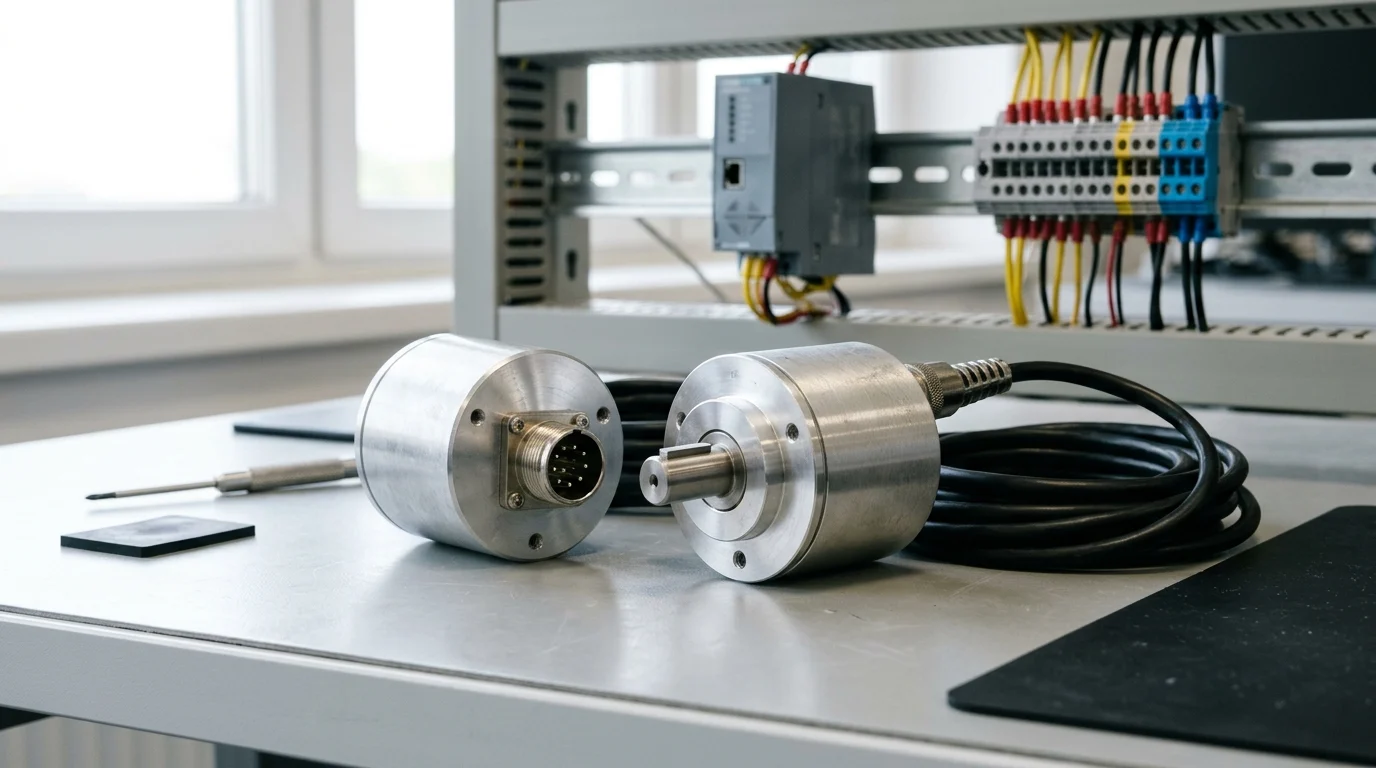
Choosing between an incremental encoder and an absolute encoder starts with how the machine axis behaves after power is removed. Incremental encoders only detect position changes when active by counting periodic patterns. Absolute encoders also supply the angle value after a startup if the value has changed when deactivated. Once power is restored, an absolute encoder can report exact position without any movement.
After power restoration, an incremental encoder needs to find an Index or home position before it can report exact position. Where rotation to find an index after a power cycle could be dangerous to equipment or people, choosing an absolute encoder ensures knowing the exact position at all times. This guide connects rotary position feedback, line drivers, and encoder cable wiring to the wider embedded control reading route and the packaging-machine sensor interface checklist.
| Engineering Check | Source Scope | Published Specification or Rule |
|---|---|---|
| Incremental active detection | Turck REI incremental encoder instructions | Incremental encoders only detect position changes when active by counting periodic patterns |
| Absolute startup angle retention | Turck REI incremental encoder instructions | Absolute encoders also supply the angle value after a startup if the value has changed when deactivated |
| Quadrature edge multiplication | POSITAL Incremental Encoder Interface | If an incremental encoder is set to 1000 PPR, a quadrature counter counts 4000 signal changes (4 signal changes each pulse) |
| Counter card minimum frequency | Turck REI incremental encoder instructions | For evaluating the output signal, Turck recommends standard input cards or counter blocks that can process a minimum pulse frequency of 80 kHz |
| Asymmetrical vs symmetrical cable length | Turck REI incremental encoder instructions | Turck recommends a maximum cable length of 10 m for asymmetrical transmission (no inverted signals) and a maximum cable length of 50 m with twisted pairs for symmetrical transmission (e.g. RS422 standard) |
| Wiegand multiturn pulse counting | POSITAL SSI Kit Encoder Manual | Wiegand pulse counting requires no external energy source, so a backup battery or complex gear systems can be eliminated |
| Sense-line input resistance | Hengstler Incremental Rotary Encoder Basics | The input resistance Ri on the power pack should amount to at least 22 MOhm so that no voltage drop occurs on the sense cables |
Power-Off Homing Loss and Quadrature Pulse Counting
Incremental encoders must restart after power-off by establishing a starting point, or index, against which to report changes in position. For an incremental encoder to report its exact position after being power cycled, the shaft must rotate until the encoder reaches Index (if it has one).
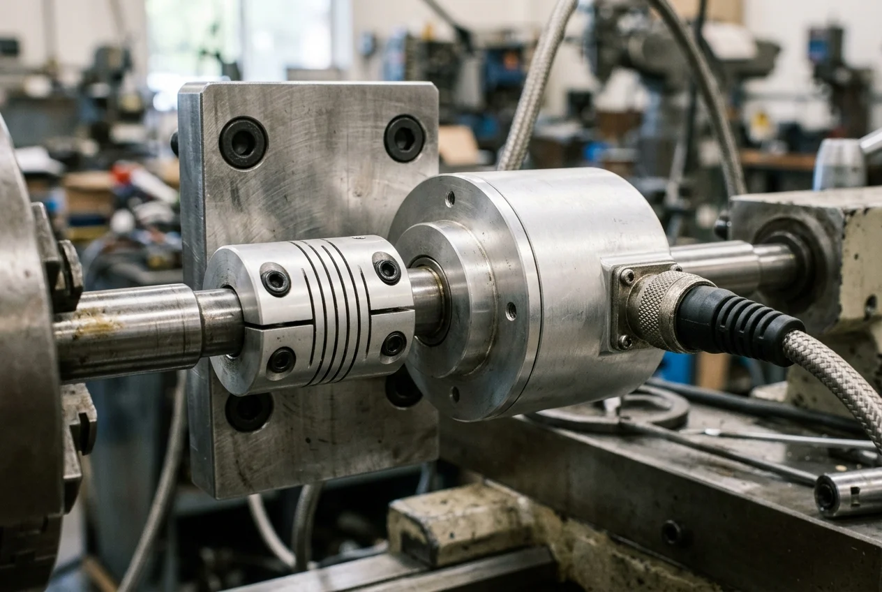
An incremental encoder typically has 2 output signals, A and B, set up with a 90° offset required for detecting rotation. Turning the incremental encoder clockwise causes the A pulse to rise 90° ahead of the B pulse, while turning the shaft counterclockwise causes the B pulse to rise ahead of the A pulse. Once every rotation, the Z signal rises for typically 90° on the exact same position for use as an accurate reference point.
Evaluating pulse resolution and counter input bandwidth requires checking both the quadrature edge multiplier and the maximum shaft speed:
- Quadrature edge counting: If an incremental encoder is set to 1000 PPR, a quadrature counter counts 4000 signal changes (4 signal changes each pulse).
- Output pulse frequency calculation: Frequency response is the maximum frequency the encoder can output via the output lines; for example, a 200 PPR encoder rotating at 600 RPM has a frequency of 2000 Hz (200*600/60s).
- Counter block input rating: For evaluating the output signal, Turck recommends standard input cards or counter blocks that can process a minimum pulse frequency of 80 kHz.
HTL Push-Pull vs TTL Differential Line Drivers
Review the supply voltage range, logic switching thresholds, and cable distance limits when matching an incremental line driver to a controller input. Push-Pull (HTL) circuits, also known as Totem Pole, provide a signal level corresponding to the applied supply voltage, which typically ranges from 8 to 30 VDC. RS422 (TTL) circuits provide a constant 5 V signal level that is not dependent on the supply voltage, with two selectable supply voltage ranges including 4.75 to 5.5 VDC.
| Line Driver Parameter | Source Scope | Published Voltage or Interface Limit |
|---|---|---|
| Push-Pull (HTL) supply and output level | POSITAL Incremental Encoder Interface | Push-Pull (HTL) circuits, also known as Totem Pole, provide a signal level corresponding to the applied supply voltage, which typically ranges from 8 to 30 VDC |
| HTL logic switching thresholds | POSITAL Incremental Encoder Interface | In HTL (high-threshold-logic), a signal above 3 V is a logic 1 and a signal less than 1 V is a logic 0, with the high output signal level dependent on the supply voltage |
| HTL High and Low output voltage limits | POSITAL Incremental Encoder Interface | For 9-30 V supply voltage, HTL High output voltage is min Supply Voltage – 3 V, and for 4.75-30 V supply voltage HTL Low output voltage is max 0.5 V |
| RS422 (TTL) supply and signal level | POSITAL Incremental Encoder Interface | RS422 (TTL) circuits provide a constant 5 V signal level that is not dependent on the supply voltage, with two selectable supply voltage ranges including 4.75 to 5.5 VDC |
| TTL logic switching thresholds | POSITAL Incremental Encoder Interface | In TTL (transistor-transistor-logic) with a 0-5 V output voltage range, a signal above 2 V is interpreted as logic 1 and a signal less than 0.8 V is interpreted as logic 0 |
| Differential pair error checking | POSITAL Incremental Encoder Interface | Controllers can compare each differential signal pair (A must be equal to inverted /A) to ensure there is no error during transmission |
| RS-422 differential and offset output voltage | Texas Instruments SLLA070D | To ensure proper drive strength, a minimum of ±2-V differential output voltage VOD and a maximum of ±3-V offset voltage VOS are measured |
| RS-422 receiver input sensitivity | Texas Instruments SLLA070D | For a common-mode voltage varying from -7 V to 7 V on an RS-422 receiver, differential input voltage VID need not be greater than ±200 mV to assume the intended state |
Differential outputs complying to the RS422 standard have the highest frequency response capability and best noise immunity when the receiver is also differential. Controllers can compare each differential signal pair (A must be equal to inverted /A) to ensure there is no error during transmission. Turck recommends a maximum cable length of 10 m for asymmetrical transmission (no inverted signals) and a maximum cable length of 50 m with twisted pairs for symmetrical transmission (e.g. RS422 standard).
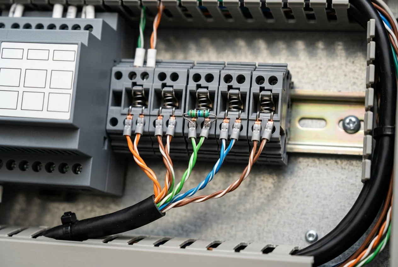
At the transceiver physical layer, RS-422 is specified as a simplex multidrop standard where only one driver and up to ten receivers can be attached to a bus. To ensure proper drive strength, a minimum of ±2-V differential output voltage VOD and a maximum of ±3-V offset voltage VOS are measured. For a common-mode voltage varying from -7 V to 7 V on an RS-422 receiver, differential input voltage VID need not be greater than ±200 mV to assume the intended state.
The termination impedance should equal the characteristic impedance of the cable, Zo, and is used only once at the end of the cable. In Texas Instruments SLLA070D Table 4, RS-422 has a maximum theoretical cable length of 1200 m and a maximum data rate of 10 Mbps. In Texas Instruments SLLA070D, as an RS-422 speed-versus-length example, a system with a cable measuring 500 m should not transmit data at speeds greater than 200 kbps. Compare these simplex differential driver limits against half-duplex fieldbus transceivers in the industrial fieldbus and transceiver interface comparison.
Singleturn vs Multiturn Absolute Encoders: Wiegand Counting, SSI, BiSS, and CANopen
Singleturn encoders measure absolute position within one revolution (360 degrees). Encoders leveraging the Wiegand effect generate energy pulses without external power, enhancing reliability and maintenance-free operation. Wiegand pulse counting requires no external energy source, so a backup battery or complex gear systems can be eliminated. In Wiegand sensors, consistent pulse width means events can be differentiated at frequencies up to 40 kHz.
Synchronous Serial Interface (SSI) and BiSS Timing and Cable Limits
In Synchronous Serial Interface (SSI), the clock is driven by the master (controller) and the data line is driven by the slave (sensor). Pause time and maximum clock rate depend on the specific manufacturer series and cable length:
- POSITAL SSI pause time: In POSITAL SSI encoders, the minimum pause time is 20 us and the maximum pause time is not limited.
- POSITAL SSI cable length vs clock rate: In POSITAL SSI encoders using RS422 twisted-pair cabling, guide cable lengths are 13 m (42 ft) at 2 MHz, 44 m (144 ft) at 1 MHz, 85 m (278 ft) at 600 kHz, 300 m (984 ft) at 200 kHz, and 750 m (2460 ft) at 80 kHz.
- EPC SSI pause time: During pause time on EPC SSI encoders, the master must wait for at least 30 µs (tm) to begin sending more clock signals or the encoder will resend the previous data.
- EPC SSI clock frequency vs cable length: EPC Absolute Series SSI encoders specify maximum clock frequency vs maximum cable length of < 2000 kHz at 4 m, < 1400 kHz at 10 m, and < 900 kHz at 25 m.
- EPC SSI extended cable clock limit: At 50 m maximum cable length, EPC Absolute Series SSI encoders specify a clock frequency of < 500 kHz.
- EPC SSI low-voltage supply cable limit: For EPC Absolute Series SSI encoders with the 5 VDC input voltage option, maximum cable length is 2 m.
For higher clock rates and cyclic delay compensation, BiSS operates cyclically at high speed up to 10 MHz with RS422 and 100 MHz with LVDS, with line delay compensation for high-speed data transfer. BiSS Safety is certified by TÜV Rheinland, follows in extracts the requirements stated in DIN EN 61784-3:2011, and can be used in safety applications up to SIL3 according to IEC61508:2010.
CANopen Encoder Profile and Bus Length Rules
Per EPC Absolute Encoders with CANopen Interface Technical Manual, the encoder is capable of CAN 2.0A and CAN 2.0B, and the implemented CANopen protocol meets the CiA 406 encoder profile. In a CAN network, the maximum length of a stub is limited to 0.5 m and the network must always be terminated on each end with 120 Ohms resistance between CANHIGH and CANLOW.
| Protocol or Parameter | Source Scope | Published Specification |
|---|---|---|
| CANopen protocol and profile | EPC CANopen Technical Manual | The encoder is capable of CAN 2.0A and CAN 2.0B, and the implemented CANopen protocol meets the CiA 406 encoder profile |
| CANopen stub length and termination | EPC CANopen Technical Manual | In a CAN network, the maximum length of a stub is limited to 0.5 m and the network must always be terminated on each end with 120 Ohms resistance between CANHIGH and CANLOW |
| CANopen long-distance bus length | EPC CANopen Technical Manual | In a CANopen system, the maximum total bus cable length is 530 m at 125 kBit/s |
| CANopen medium-speed bus length | EPC CANopen Technical Manual | In a CANopen system, the maximum total bus cable length is 270 m at 250 kBit/s |
| CANopen high-speed bus length | EPC CANopen Technical Manual | In a CANopen system, the maximum total bus cable length at 1 MBit/s is <40 m |
| Programmable incremental resolution object | POSITAL CANopen User Manual | The maximum possible incremental resolution value is 14 bit, which means 16384 pulses per revolution PPR |
Encoder Cable Wiring: Twisted Pairs, Sense Lines, and Shield Grounding
Follow the manufacturer wiring diagram and power-supply filtering rules when terminating an encoder cable in a control cabinet. In Turck REI incremental encoder wiring diagrams, Pin 1 is GND, Pin 2 is UB +, Pin 3 is A, Pin 4 is A inv., Pin 5 is B, Pin 6 is B inv., Pin 7 is Z, Pin 8 is Z inv., and PH is shield. Per Turck REI incremental encoder instructions, devices with high noise levels (e.g. frequency converters, solenoid valves, or contactors) must not be connected to the encoder power supply unless suitable voltage filtering is in place. When specifying line filters for shared cabinets, evaluate attenuation stages using the common-mode vs. differential-mode EMI filter selection guide.
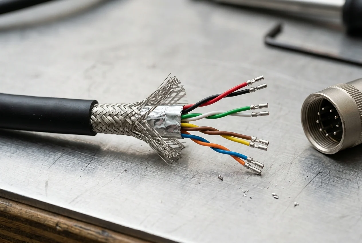
On encoders equipped with remote voltage-sense leads, the present input voltage Uin is output to the Sense VCC and Sense GND cables and returns as data to the power pack. The input resistance Ri on the power pack should amount to at least 22 MOhm so that no voltage drop occurs on the sense cables.
Shield termination must follow the documented grounding configuration for the cordset and receiver:
- Single-ended receiver shield grounding: When connecting cable shields to the receiver/instrument ground, do not connect the end near the encoder, because connecting the shield at both ends can cause ground loops.
- Protection against machine ground currents: High motor/machine ground currents flowing through the encoder wiring could potentially damage the encoder and associated equipment.
- Non-CE cordset shield connection: For Non-CE cords, the shield is not connected to the coupling nut on the encoder end of the cable, and it is grounded on the controller end.
- CE cordset boundary: EPC recommends that the CE cordset is only used when the application requires it in order to avoid harmful grounding loops.
Sources
- Turck — Encoders Technical Guide
- POSITAL — Incremental Encoder Interface
- POSITAL — What Is an Encoder?
- POSITAL — Wiegand Sensors
- POSITAL — SSI Encoders
- POSITAL — Absolute Kit Encoders with SSI Interface Manual
- POSITAL — BiSS Interface Encoders
- POSITAL — Absolute IXARC Encoders with CANopen Interface User Manual
- Hengstler — Incremental Rotary Encoder Basics with Sense Lines
- Texas Instruments — Differential Standards Overview and System Configurations
- Encoder Products Company — Understanding EPC SSI Encoders Technical Bulletin
- Encoder Products Company — Circular Connector Options Technical Bulletin
- Encoder Products Company — Absolute Encoders with CANopen Interface Technical Manual
- Encoder Products Company — What is the Difference Between an Absolute and Incremental Encoder?
- US Digital — What is the Difference Between Incremental and Absolute Encoders?